+91 99980 88430 | +91 95589 17778
 info@convello.in | sales@convello.in

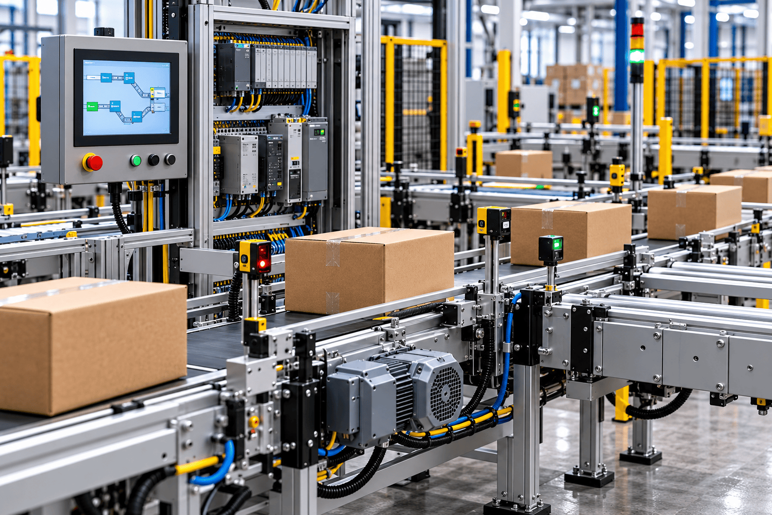
At 2:47 p.m., the packaging line looks mechanically healthy. The belts are tracking, the motors are not overloaded and every guard is in place. Yet cartons are building up before the palletiser. The upstream conveyor says it is ready. The downstream machine says it is not blocked. The HMI displays “Zone 14 fault,” but the operator cannot tell whether the problem is a photo-eye, a full destination, a missing handshake or a safety condition that has not been reset.
Maintenance checks the drive. Production checks the cartons. The controls engineer opens the PLC program. Each person is looking at a valid part of the system, but nobody has one clear description of what the line is waiting for.
| THE HUMAN REALITY The conveyor was not broken. The conversation between machines was. |
This opening is an illustrative plant-floor composite, not a claimed Convello customer incident. It reflects one of the most common reasons an automated conveyor line feels unreliable even when its mechanical components are in good condition: the sequence, ownership and recovery logic were never made clear enough for the people operating and maintaining it.
What Is a Conveyor Control System?
A conveyor control system is the combination of electrical hardware, software and operating rules that controls product movement. It decides when equipment may start, which destination is available, how fast a conveyor should run, whether products may accumulate, when a transfer may lift, and what must happen after a fault, power interruption or emergency stop.
Depending on the application, the system may include simple contactors and limit switches, a distributed motorised-roller controller, one or more PLCs, variable-frequency drives, a safety controller, operator HMIs, barcode or RFID readers, and interfaces to WMS, WCS, MES or ERP systems. The correct architecture is not determined by the number of devices alone. A short conveyor between two machines can require sophisticated handshake and safety logic, while a long gravity conveyor may need very little control.
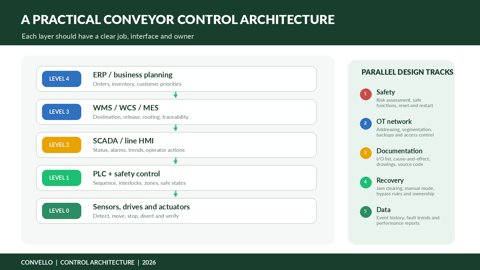
Figure 1. A practical conveyor control architecture separates device-level control, PLC sequence, operator visibility and higher-level business decisions.
The Six Layers of a Practical Control Architecture
1. Sensors and field devices
Photo-eyes, proximity switches, encoders, limit switches, pressure switches, barcode readers, RFID readers, weigh scales and safety devices describe what is happening in the physical line. Their job is not simply to generate an electrical signal. Each device should support a defined decision: product present, transfer home, guard closed, speed confirmed, destination clear or load identified.
2. Drives and actuators
Motors, motor starters, VFDs, motorised rollers, brakes, pneumatic cylinders, lift tables, pop-up transfers and diverters create movement. The controls design must define permitted speed, acceleration, direction, torque or current limits, stopping behaviour and feedback. A command without confirmation is only an assumption.
3. Local or distributed zone control
In roller conveyor systems, local zone controllers can manage motor-driven rollers and sensors close to the conveyor. This can reduce central I/O wiring and support zero-pressure accumulation. Interroll, for example, describes MultiControl as a controller that can connect multiple RollerDrives and sensors, operate conveyor zones, and communicate with a PLC over industrial networks. The design question is whether the local controller owns complete zone behaviour or only executes commands from the PLC.
4. PLC and safety control
The PLC coordinates sequence, interlocks, timing, routing and interfaces. Safety-related functions may be implemented through a safety relay or safety PLC, depending on the risk assessment and architecture. Standard control and safety control must cooperate, but safety functions should not be treated as ordinary production logic.
5. HMI and SCADA
The HMI shows operators what the system is doing and what action is expected. SCADA or line-monitoring software may add trends, alarm history, energy data and remote supervision. A useful display translates logic into operating language: “Carton did not reach palletiser in 8 seconds” is more useful than “Timer T14 done.”
6. WMS, WCS, MES and ERP interfaces
Higher-level systems may release work, provide a product destination, confirm an order, store traceability data or monitor performance. ISA-95 provides a framework for separating enterprise, manufacturing-operations and control-system responsibilities. The exact software names vary by site, so every project should define responsibilities in plain language rather than assuming that “the WMS will handle it.”
What Each Control Component Should Own
| Component | Primary responsibility | Typical questions |
| Sensor | Detect a physical condition | What is present? Where is it? Is the state stable and believable? |
| Motor starter | Switch a fixed-speed motor | May the motor run, and has overload protection remained healthy? |
| VFD | Control speed, ramping and drive diagnostics | What speed is required? Is current, torque or fault status abnormal? |
| Zone controller | Manage local rollers and accumulation | May this zone accept, hold or release a load? |
| PLC | Coordinate sequence and interlocks | What should happen next, and what conditions must be true? |
| Safety relay / safety PLC | Perform validated safety functions | What hazardous motion must stop, and what is required before reset? |
| HMI | Explain status and support permitted actions | What happened, where, and what safe response is expected? |
| WCS / MES / WMS | Coordinate work and destination data | Which load should move where, and what confirmation is required? |
PLCs: The Sequence Owner
A PLC is often described as the “brain” of the conveyor, but that description can hide an important issue: a PLC only controls what has been clearly defined and tested. If the project team has not agreed on blocked states, manual recovery, queue priorities or equipment ownership, the program will encode assumptions that surface during commissioning.
A robust conveyor PLC program normally separates reusable equipment modules from line-level sequence. A conveyor zone may have standard commands and states such as available, occupied, running, blocked, faulted and inhibited. The line-level logic then coordinates those zones with scanners, transfers, machines and destinations.
- Use consistent names for zones, devices and alarms.
- Separate command, permissive, interlock and feedback signals.
- Create timeouts for expected movement, but avoid treating every delay as the same fault.
- Record first-out fault information so the original cause is not hidden by downstream alarms.
- Define automatic, manual, maintenance and recovery modes explicitly.
- Control restarts deliberately after power loss, emergency stop or communication failure.
Sensors: Every Device Must Support a Decision
Adding more sensors does not automatically make a conveyor smarter. A sensor creates value when its location, target, response time, failure behaviour and owner are understood. A photo-eye placed where cartons wobble may generate false alarms. A proximity switch that confirms a transfer is raised may not confirm that the product actually moved. A barcode reader can identify a carton but cannot decide what to do when the label is unreadable unless an exception route exists.
| Sensor / signal | Useful decision | Common design mistake |
| Photo-eye | Product present, zone occupied, gap confirmed | Mounting where loose film, vibration or product skew creates unstable detection |
| Encoder / speed switch | Actual movement and speed confirmation | Assuming a motor command proves that the belt or rollers moved |
| Limit / proximity switch | Transfer, gate or stop position | Using one switch where both home and work positions require confirmation |
| Barcode / RFID | Identity and destination | No defined no-read, duplicate-read or wrong-product route |
| Motor current / drive data | Increasing drag, overload or stalled motion | Collecting data without thresholds or maintenance ownership |
| Safety device | Guard, light curtain, pull cord or E-stop state | Displaying only a general safety fault without showing the affected zone |
Motor Starters, VFDs and Motorised Rollers
A fixed-speed motor starter is often suitable for a simple conveyor that only needs reliable start and stop control. A VFD becomes valuable when the process needs adjustable speed, controlled acceleration, reduced mechanical shock, reverse operation, torque or current visibility, or coordinated speed changes. It should not be added only because it is considered “more advanced.”
For unit-load roller conveyors, motorised rollers and distributed zone controllers can reduce energy use and allow products to accumulate without contact. The controls philosophy must still define who owns zone release, how a blocked destination is communicated, and what the PLC should do if one local controller loses communication.
| PRACTICAL RULE Select the drive architecture around the required movement and diagnostics. Then define what happens when the drive is unavailable, not ready, in local mode or unable to confirm motion. |
HMI Design: Tell People What Happened and What They May Do
An HMI is not a decorative screen placed on the control panel after programming is complete. It is the operating conversation between the control system and the people responsible for production. When the conveyor stops, the operator needs more than a red banner. The message should identify the location, the failed condition, the effect on flow and the permitted next action.
| Weak message | Better message | Why it helps |
| Sensor 14 fault | Carton did not clear Zone 14 within 8 seconds. Check the transfer after a safe stop. | Names the product condition, location and expected action. |
| Drive fault | Pallet conveyor Drive P-04 is not ready. Upstream release is inhibited. Maintenance access required. | Explains the consequence and ownership. |
| Destination blocked | Lane 3 is full. New cartons are accumulating in Zones 21-26. Clear the lane or select the approved alternate route. | Connects the condition to material flow. |
| Safety fault | South-side pull cord between Zones 8 and 10 is active. Reset is permitted only after the route is checked and cleared. | Shows the affected area and prevents blind reset. |
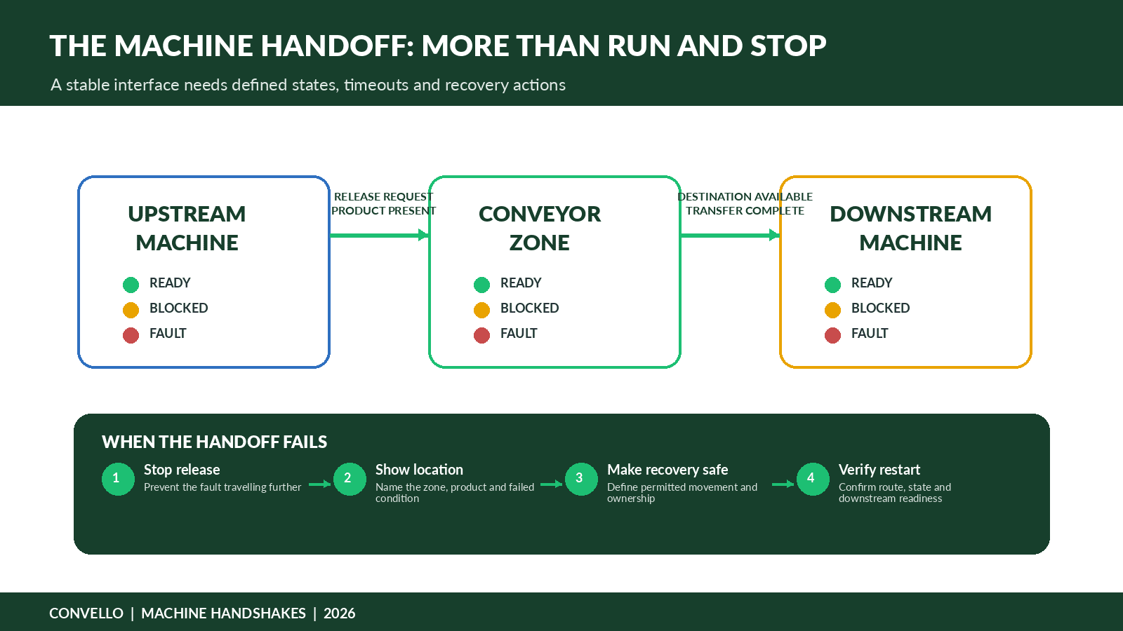
Figure 2. A machine handoff requires defined states, timeouts and recovery actions – not only RUN and STOP commands.
Machine Handshakes: The Conversation That Controls Flow
A machine handshake is the agreed set of signals and rules used by two pieces of equipment to transfer a product safely and predictably. The exact signal names vary, but the underlying questions remain consistent:
- Is the downstream machine ready to receive?
- Is a product available to release?
- Has the destination reserved capacity for that product?
- Did the product leave the upstream conveyor?
- Did it arrive at the downstream confirmation point?
- Who owns the product while it is between the two machines?
- What happens when confirmation does not arrive within the expected time?
- What happens after a fault is cleared: automatic retry, operator confirmation or manual recovery?
The last two questions are where many commissioning problems begin. If both machines wait for the other to act, the line deadlocks. If both release without reservation, products collide or a full destination overflows. If a timeout only produces a generic alarm, operators may reset the system repeatedly without resolving the original condition.
Operating Modes and States
Modes describe how the system is being controlled. States describe what the equipment is currently doing. Keeping the two concepts separate makes programs easier to understand and alarms easier to explain.
| Category | Examples | Design questions |
| Operating modes | Automatic, manual, local, maintenance, commissioning | Who may select the mode? What movements are allowed? What safeguards remain active? |
| Equipment states | Stopped, starting, running, occupied, blocked, starved, faulted, inhibited | What causes each state? What output is expected? How is the state cleared? |
| Safety states | Safe stop, guard open, E-stop active, reset required | Which motion is removed? Where is reset located? How is unexpected restart prevented? |
| Communication states | Connected, stale data, device missing, fallback | Does the system stop, hold, degrade or allow controlled manual operation? |
WMS, WCS and MES Integration: Define the Boundary
A warehouse or manufacturing project often includes several software layers. One system may create the order, another may decide the route, and the PLC may control the physical movement. Problems develop when the boundary between these decisions is not written down.
For example, the WMS may provide a destination code, while the WCS reserves a route and the PLC verifies that the selected divert is physically available. If the barcode is unreadable, the PLC may send the load to a no-read lane and report the exception. If that lane is full, the WCS may pause new releases. The responsibility chain should be documented for normal flow, missing data, duplicate data, destination-full conditions and communication loss.
| INTEGRATION PRINCIPLE Higher-level software should request or authorise material movement. The control system should verify that the physical route is available and execute the movement safely. |
Safety Control Is Not Production Logic with a Red Icon
Conveyor controls must be developed with machinery risk assessment, guarding and access design. ISO 12100 provides a risk-assessment and risk-reduction framework, while ISO 13849-1 addresses safety-related parts of control systems. These are reference frameworks, not a substitute for project-specific engineering or applicable Indian requirements.
Emergency stops, pull cords, guard interlocks, light curtains and safe torque-off functions should be assigned to defined safety zones. The design must explain which motion stops, what stored energy remains, how the area is checked, where reset is permitted and how unexpected restart is prevented. A production PLC may display the safety state, but it should not bypass or recreate the safety function in standard code.
OT Network and Cybersecurity
As conveyor controls connect to plant networks, remote support tools and business software, cybersecurity becomes part of reliability. The ISA/IEC 62443 series provides a framework for industrial automation and control-system security, including risk management, zones and conduits, access control and lifecycle responsibilities.
- Create an asset and network diagram.
- Separate industrial devices from general office traffic.
- Control remote access and record who can change logic or drive parameters.
- Back up PLC, HMI, drive, scanner and controller configurations.
- Define patching, replacement and end-of-life responsibilities.
- Use managed change control so a temporary commissioning bypass does not become an undocumented permanent condition.
Public Project Case Study 1: Ken’s Foods Pallet-Conveying Controls
In July 2026, Rockwell Automation published a case study describing how Ken’s Foods modernised end-of-line pallet conveying using an on-machine control architecture. The project placed variable-frequency drives and other control components closer to the conveyor rather than concentrating everything in large central panels.
Rockwell reported that the architecture supported a 130-drive palletising line, reduced cabling and panel complexity, and provided real-time visibility into values such as current, voltage and speed. An electrical project partner estimated an overall 17% cost saving compared with a conventional central-panel approach. Ken’s Foods also adopted the approach as a standard for future pallet-conveying applications.
The useful lesson is not that every conveyor should use the same hardware. The project shows how physical architecture, diagnostics, safety networking, maintenance access and future expansion can be designed together. Locating control closer to machinery may shorten wiring and improve troubleshooting, but it also requires disciplined network design, environmental suitability, addressing, backups and device ownership.
Public external project source: Rockwell Automation, “Ken’s Foods Modernizes Palletizing System with Rockwell Automation On-Machine Design,” published 22 July 2026. This is not a Convello customer installation.
Public Project Case Study 2: Kasa Baggage-Handling Virtual Commissioning
A second public project shows why conveyor controls should be tested before the physical line is fully available. Kasa Controls & Automation used a dynamic digital twin to connect and test PLC and SCADA code for baggage-handling systems. The virtual model included conveyor speed, acceleration, gravity, friction, wiring and I/O behaviour, allowing fault scenarios to be tested during factory acceptance.
Rockwell reported that a startup initially planned for four to six weeks was completed in six days. The important lesson is not the exact duration. It is that conveyor logic can be tested against product behaviour, sensor timing, merges, emergency stops and exception scenarios before the site schedule becomes compressed.
Public external project source: Rockwell Automation, “Faster BHS Commissioning Takes Off with Kasa,” published 15 November 2021. This is not a Convello customer installation.
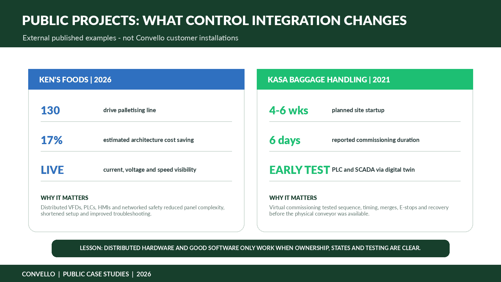
Figure 3. Two public projects illustrate how controls architecture and early testing can affect installation, troubleshooting and scalability.
Illustrative Indian Project: Packaging Line to Pallet Dispatch
Consider an illustrative Indian FMCG plant that wants to connect two packing lines to two palletisers, a stretch wrapper and a dispatch conveyor. The existing system has separate local panels, inconsistent alarm text and no common method for handling a full palletiser lane. Operators frequently move cartons to temporary floor stacks when a destination is unavailable.
A practical control concept could include 24 conveyor zones, four cross transfers, two barcode readers, VFD-controlled merge conveyors, local motorised-roller controllers, one line PLC, a safety PLC, two HMIs and an interface to the plant’s production system. The key design work is not the device count. It is the definition of routing, reservation and recovery.
| Operating situation | Required control response |
| Palletiser 1 ready | Reserve a route, release the current carton group and confirm arrival. |
| Palletiser 1 blocked | Hold new releases, accumulate within defined zones and consider the approved alternate routing. |
| Barcode no-read | Send the carton to an accessible exception lane and record the event. |
| Transfer does not reach work position | Stop the affected movement, protect upstream release and show a location-specific alarm. |
| Safety pull cord active | Place the defined zone in a safe state, prevent automatic restart and require deliberate reset after inspection. |
| Production-system communication lost | Complete permitted in-process movements, stop new releases and display the degraded operating mode. |
For this example, the project team should agree a cause-and-effect matrix before programming begins. Every destination-full, sensor-failed, drive-not-ready, communication-lost and safety condition should have a defined response. That document becomes a common reference for production, mechanical design, electrical design, PLC programming, HMI development and testing.
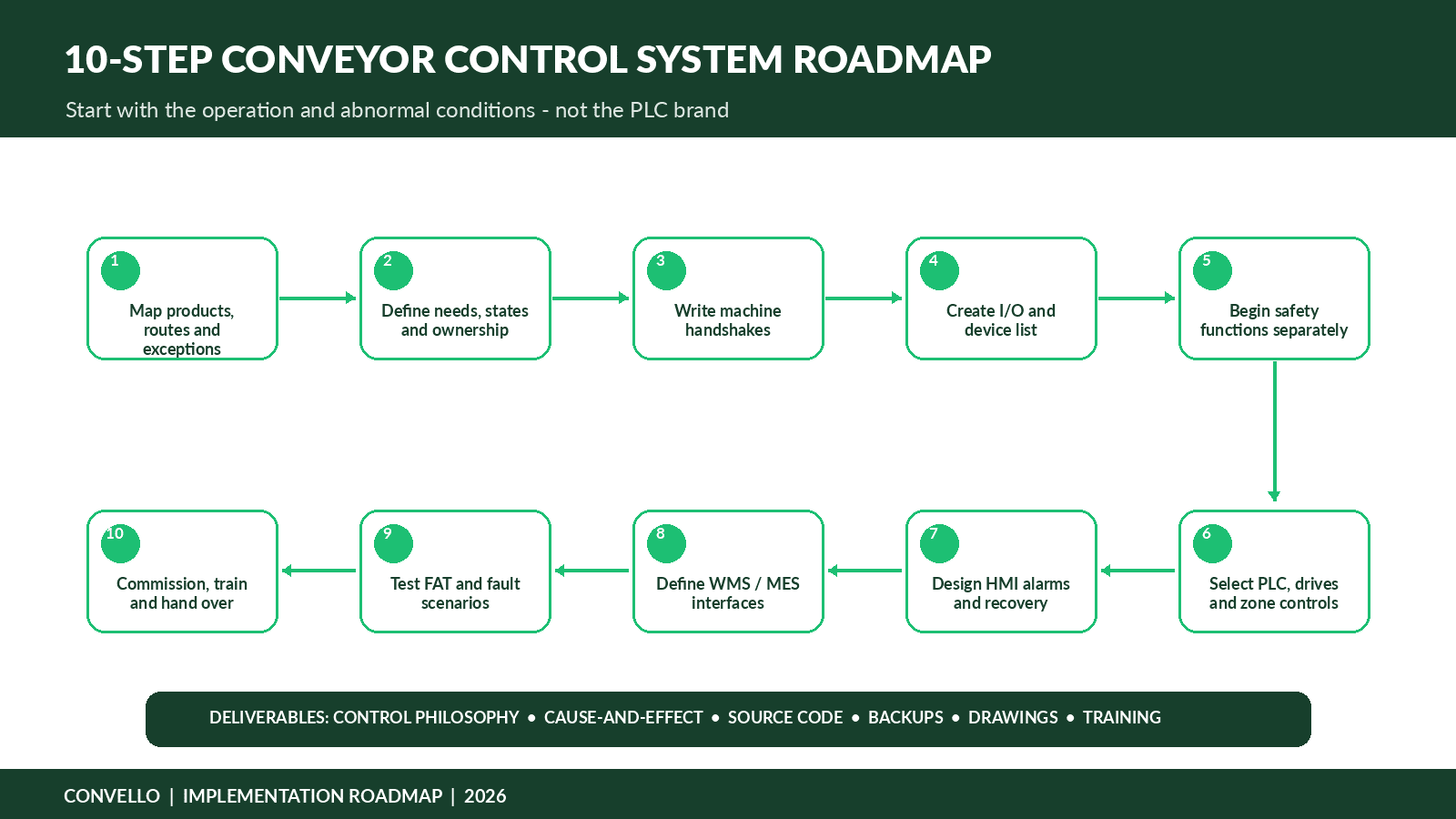
Figure 4. A requirement-led implementation roadmap begins with material flow and abnormal conditions, then selects and validates the controls architecture.
A 10-Step Conveyor Control System Roadmap
- Map products, routes, destinations, rejects, rework and recovery paths using actual operating observations.
- Define operating modes, equipment states, ownership and the conditions that permit movement.
- Write the handshakes between conveyors, machines, scanners, robots and higher-level software.
- Create the I/O list, device naming convention, network map and cause-and-effect matrix.
- Complete machinery risk assessment and design safety functions separately from standard control logic.
- Select PLC, safety hardware, VFDs, starters, zone controllers, HMIs and network architecture based on the required functions.
- Design alarms, operator actions, manual controls, recovery permissions and restart behaviour.
- Define the data exchanged with WMS, WCS, MES, ERP or plant systems, including failure and retry behaviour.
- Test normal flow, peak flow and fault scenarios during FAT; use emulation when system complexity justifies it.
- Commission in stages, train users, record final settings, provide source code and backups, and complete a controlled handover.
Factory and Site Acceptance Tests That Matter
A conveyor should not pass acceptance only because products moved from one end to the other. Testing should include abnormal conditions and recovery, because those are the situations that determine whether the line remains usable after commissioning.
| Test scenario | What to verify |
| Normal production at sustained peak rate | Stable spacing, routing, sensor detection, drive loading and downstream acceptance. |
| Destination becomes full | Upstream release stops correctly, accumulation remains controlled and the HMI identifies the affected route. |
| Product fails to reach the next sensor | Timeout identifies the correct zone; adjacent equipment does not create a secondary jam. |
| Barcode or RFID no-read | Product follows the defined exception route and the event is reported once. |
| Drive or local controller loses communication | System enters the defined safe or degraded state and identifies the exact device. |
| E-stop or guard interlock operates | Required hazardous motion stops; reset does not cause unexpected restart. |
| Power is restored after outage | System reconciles occupied zones and in-process products before release. |
| Manual mode is selected | Only permitted movements are possible, at the intended speed and with clear operator control. |
| Higher-level system is unavailable | The line follows the approved fallback rather than silently losing routing or identity data. |
| Backup is restored to replacement hardware | Addresses, parameters, safety signatures and source versions are verified. |
Documentation and Source-Code Ownership
A control system remains maintainable only when the final delivered configuration is documented. Many plants receive electrical drawings but not the exact PLC, HMI, drive or scanner files that were used at handover. Others receive source code without passwords, software versions or a tested restore procedure.
- Approved control philosophy and cause-and-effect matrix
- Final I/O list and device tag list
- Electrical drawings and network architecture
- PLC, safety PLC, HMI and SCADA source files
- Drive, motorised-roller controller, scanner and vision-system backups
- Software versions, licences, passwords and access ownership
- Alarm list and operator response guidance
- FAT, SAT and safety-validation records
- Critical spare-parts list
- Change log and final as-built settings
- Training materials and support escalation contacts
Common Conveyor Control System Mistakes
| Mistake | Why it causes trouble | Better approach |
| Programming before flow is agreed | Software encodes assumptions and commissioning becomes design work. | Freeze routes, states, ownership and exception handling first. |
| Using generic alarms | Operators reset symptoms without finding the originating condition. | Name the location, failed condition, consequence and permitted action. |
| No first-out fault capture | A chain of secondary alarms hides the original event. | Record the earliest relevant cause and event timestamp. |
| Treating manual mode as unrestricted motion | Recovery creates new hazards and product collisions. | Define permitted manual movements, speeds, hold-to-run rules and access. |
| No communication-loss strategy | The line may continue with stale routing or stop in an unsafe position. | Define safe, hold and degraded states for every interface. |
| Safety added after programming | Guarding, reset and zone boundaries conflict with the mechanical layout. | Develop risk assessment, access and controls architecture together. |
| No source-code handover | Small future changes require reverse engineering or vendor dependency. | Specify editable files, backups, passwords and restore testing in the contract. |
| FAT tests only normal flow | Major logic defects appear during site startup. | Test full lanes, missing products, no-reads, jams, E-stops and power recovery. |
Information to Share for a Conveyor Controls Quotation
- Product dimensions, weight, orientation and accepted packaging condition
- Required routes, destinations, reject and rework paths
- Normal, sustained peak and short-burst throughput
- Conveyor and machine layout with elevations and access areas
- Existing motor, drive, sensor, panel and network details
- Upstream and downstream machine signal lists or manuals
- Required operating modes and manual recovery expectations
- Barcode, RFID, weighing, vision or traceability requirements
- WMS, WCS, MES, ERP or production-system interface details
- Site electrical supply and preferred industrial network
- Safety standards, client specifications and risk-assessment responsibilities
- HMI, language, alarm history and reporting requirements
- FAT, SAT, simulation or virtual-commissioning expectations
- Source-code, cybersecurity, remote-support and backup requirements
- Future expansion plans and approved component standards
Frequently Asked Questions
What is the difference between a conveyor control panel and a conveyor control system?
The panel is the physical enclosure containing some electrical components. The control system includes field devices, drives, software, safety functions, networks, HMIs and external interfaces, whether they are panel-mounted or distributed along the conveyor.
Does every conveyor need a PLC?
No. A simple fixed-speed conveyor may use basic controls, while a local zero-pressure accumulation controller may operate without a central PLC. A PLC becomes useful when sequencing, routing, machine interfaces, reporting or complex recovery is required.
When should a conveyor use a VFD?
Use a VFD when adjustable speed, controlled acceleration, reverse movement, coordinated process speed, drive diagnostics or another application-specific function justifies it. A fixed-speed starter may be simpler for basic duties.
What is a conveyor machine handshake?
It is the defined exchange of readiness, request, release, completion, blocked and fault signals between adjoining machines or systems.
What does a WCS do in a conveyor system?
A warehouse control system commonly coordinates routing and equipment execution between warehouse software and PLC-controlled material-handling equipment. Exact responsibility varies, so the interface must be defined for the project.
Can a conveyor PLC connect to a WMS or MES?
Yes, usually through a WCS, middleware, OPC UA, database, API or industrial communication gateway. The data model, timing, retry and failure behaviour should be agreed before implementation.
What information should an HMI alarm show?
It should identify what happened, where it happened, the effect on material flow, and the safe or permitted next action. It should avoid exposing only internal program tags.
What happens if a conveyor sensor fails?
The response depends on the sensor’s function and risk. The system may stop the affected zone, inhibit release, enter a degraded mode or require manual recovery. The design should not assume that a failed sensor simply means no product.
Can old conveyor controls be upgraded?
Often yes, when the mechanical equipment remains suitable and its interfaces can be documented. The project should review motors, wiring, safety, sensors, network, panels, spare parts and the availability of original drawings and source code.
What is virtual commissioning?
Virtual commissioning connects real or representative control code to a simulated model of the conveyor and product flow. It allows sequences, timing and fault scenarios to be tested before the physical system is ready.
Who should own conveyor PLC source code?
Ownership and licensing should be agreed contractually. The plant should at least receive the editable files, final version, software requirements, passwords or access process, and a tested backup and restore method.
What should be included in conveyor FAT?
FAT should test normal and peak flow, blocked destinations, missing products, sensor failures, drive faults, E-stops, communication loss, manual mode, power recovery, alarm text and data interfaces.
Conclusion: Control the Conversation, Not Only the Conveyor
A reliable conveyor control system does more than energise motors. It coordinates people, products, machines and software through clearly defined states and interfaces. It shows operators what the line is waiting for. It gives maintenance teams useful evidence. It handles blocked destinations and missing confirmations without creating a second problem. It separates safety functions from production logic and preserves the information needed to support the system years after commissioning.
The strongest project begins with actual material flow and abnormal operating conditions. Write the handshakes. Define ownership. Design the HMI around human recovery. Test faults before startup. Hand over editable files and verified backups. Hardware choices matter, but clarity is what turns the components into a dependable system.