+91 99980 88430 | +91 95589 17778
 info@convello.in | sales@convello.in

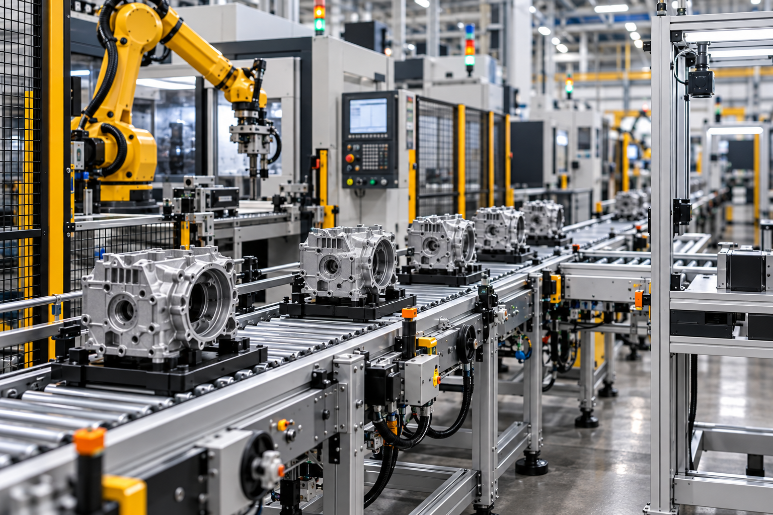
At 10:42 a.m., the CNC cell has finished another housing. Its green light is on. The next part should move to washing, then inspection and laser marking. Instead, the outfeed tray is full. The washer is waiting for an operator to confirm the previous batch. The inspection bench has two red-tagged parts with no defined rework route. A production operator leaves the cell, carries a plastic bin across the aisle and asks someone where the parts should go.
From the control room, the machines appear available. On the floor, useful production has paused. Nothing dramatic has failed. The loss is happening in the space between machines – at the handoff, in the queue and in the lack of a shared rule about who may release the next part.
This is where many manufacturing conveyor automation projects begin. The conversation starts with conveyor length, speed and motor power. The daily problem, however, is usually less tidy: operators walking because a trolley is missing, parts stacked in the wrong order, a buffer that fills before tea break, a scanner that rejects a label but has nowhere to send the product, or a line that can stop safely but cannot restart calmly.
A conveyor can remove walking. It cannot remove confusion. Good automation makes the process easier to understand on a normal day and easier to recover on a difficult one. It connects material movement, machine states, operator decisions, quality routes, maintenance access and safety into one practical operating system.
| Practical rule Do not begin with, “How fast can the conveyor run?” Begin with, “Where does the product wait, who is allowed to release it, what happens when the next machine stops, and how does the team recover without improvising?” |
What Is Manufacturing Conveyor Automation?
Manufacturing conveyor automation is the coordinated movement and control of components, subassemblies, containers, fixtures, pallets or finished goods between production processes. It may include belt, roller, slat-chain, pallet, indexing, lift, transfer or assembly conveyors, but the equipment is only one layer.
The complete system can include sensors, variable-speed drives, pneumatic stops, scanners, PLC logic, safety controls, HMI screens, machine handshakes, recipe settings, traceability and interfaces to robots, test equipment, MES or other plant systems. The purpose is not simply to replace a person who pushes a trolley. It is to create a repeatable flow that the operation can understand, maintain and improve.
The word coordinated matters. A powered roller conveyor that delivers ten totes to a machine with room for four does not improve flow. A sensor that detects a full buffer but does not stop upstream release only creates a warning. A PLC that records every fault but gives operators no clear recovery steps produces data without control.
The most useful manufacturing automation is often less glamorous than the sales presentation. It may be a short powered section between two machines, three accumulation zones, a rework spur and a simple ready-blocked-faulted handshake. When those details remove daily friction, the result can be more valuable than a complex system that nobody trusts.
Stabilize the Process Before You Automate It
Automation amplifies whatever process it receives. If the product route changes by operator preference, if quality decisions are inconsistent, if fixtures arrive in several conditions or if the upstream and downstream teams disagree about ownership, a conveyor will move the uncertainty faster.
Before selecting equipment, watch the process through start-up, normal production, breaks, changeovers, faults and shift end. Speak with the operators who rescue the line, the maintenance technicians who clear it and the quality team that handles exceptions. Their improvised routines often reveal the real design requirements.
Look for handwritten marks, temporary tables, spare bins, blocked walkways, products placed on the floor, sensors covered with tape, guards that are removed too often, and people who must shout across the line before starting a machine. These are not small observations. They are clues that the future system needs a clearer route, better access or a defined operating rule.
Stabilization does not mean making the process perfect before investing. It means understanding what must be fixed by process design, what should be mechanized and what genuinely requires coordinated automation.
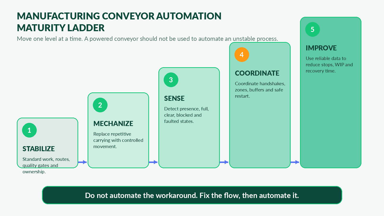
Manufacturing conveyor automation maturity ladder: stabilize, mechanize, sense, coordinate and improve.
Five Practical Levels of Conveyor Automation
| Level | What it adds | Typical trigger |
| 1. Stabilize | Standard routes, defined quality gates, known product conditions and clear ownership. | When people solve the same problem differently every shift. |
| 2. Mechanize | Powered movement or gravity flow replaces repetitive carrying, pushing or lifting. | When the route is stable but manual transport consumes time or creates strain. |
| 3. Sense | Presence, clear, full, blocked, fault and identification signals become visible. | When the line needs reliable awareness of product and equipment condition. |
| 4. Coordinate | PLC zones, machine handshakes, buffers, interlocks and safe restart logic control flow. | When multiple machines must share capacity and respond to one another. |
| 5. Improve | Reliable event and production data supports loss analysis, maintenance and controlled changes. | When the operating discipline is mature enough to act on the data. |
Not every plant needs the fifth level on day one. A phased design can reserve panel space, network capacity, sensor mounts and software structure for future expansion while delivering a simple first stage that operators can trust.
Map the Real Material Flow – Not the Ideal Drawing
A layout drawing usually shows the intended route. A useful process map shows what actually happens when the route is interrupted. Walk one product from the first stable handling point to finished goods. Record every touch, wait, rotation, queue, inspection, identification step and transfer of responsibility.
Do not stop at machine boundaries. Watch what happens between them. Does a fixture need to be opened? Is oil drained before washing? Does the part cool before inspection? Is the barcode visible from the next scanner? Can a rejected unit re-enter after correction without losing traceability? Is an empty tote returned against the product flow?
The map should separate normal flow from exception flow. Normal flow explains how a good product advances. Exception flow explains what happens to a damaged item, a no-read code, a test failure, a full downstream buffer, a machine fault, an incorrect fixture, a late order or a product that requires manual review.
A system that only handles the normal route will appear efficient during a demonstration and become frustrating in daily production. The difficult conditions are not unusual events. They are part of the process.
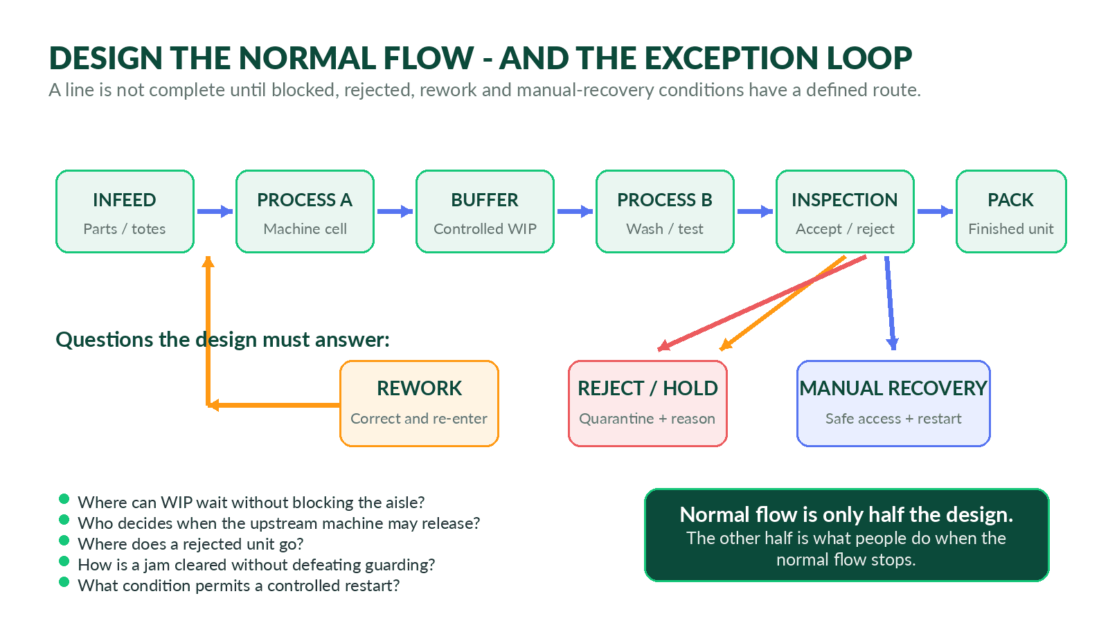
Normal manufacturing flow must be designed together with rework, reject and manual-recovery routes.
Fifteen Decisions That Shape the Final System
1. Define the complete product envelope
Record the smallest, largest, lightest, heaviest and least stable product or carrier. Include overhang, centre of gravity, underside condition, orientation and any loose features. The product that causes trouble is often not the heaviest one; it may be the smallest part that bridges a transfer or the tallest assembly that becomes unstable during a stop.
2. Separate demand rate from equipment speed
Calculate required output from available production time and demand, then compare it with real cycle times, quality losses and planned changeovers. Conveyor speed should support sustainable flow and recovery. Running every section faster can increase impact, noise, spacing errors and downstream pressure without increasing finished output.
3. Identify the true constraint
The line capacity is limited by the slowest recoverable process, not by the fastest conveyor. Measure blocked time, starved time, process cycle, operator delay and fault recovery at each station. A conveyor project should protect the constraint and prevent avoidable starvation or blockage.
4. Choose the correct conveying surface
Belt conveyors provide continuous support for varied parts and packages. Roller conveyors work well for stable, flat-bottom loads and can create controllable zones. Slat or tabletop chains suit rigid containers and some assembly applications. Pallet conveyors support heavy fixtures and unit loads. Selection must reflect the product base, transfer points, process environment and required control.
5. Engineer every transfer point
The handoff between conveyors or machines deserves as much attention as the straight section. Check support across the gap, speed matching, height, product orientation, guide transitions, sensor position and access for clearing. A product that travels perfectly for twenty metres can still fail at a twenty-millimetre gap.
6. Design buffers around interruptions
Buffers should absorb known short stops and protect critical processes, not hide chronic failure. Define what event fills the buffer, what stops upstream release, what indicates full, how the line recovers and how much WIP is acceptable. Buffer capacity should be expressed in both positions and minutes of production.
7. Define normal, rework, reject and hold routes
A rejected product needs a physical destination and a data status. Decide whether it can be reworked, inspected again, scrapped or quarantined. Provide safe access, adequate capacity and confirmation that the item actually reached the intended route.
8. Plan workstation ergonomics
Automation should reduce unnecessary walking and awkward handling without forcing operators into a fixed poor posture. Define working height, reach, product presentation, tool access, lighting, replenishment, empty-container return and the space required for people to step away safely.
9. Write the machine handshake
For each interface, agree the meaning of ready, blocked, starved, running, faulted, product present, product accepted and release permitted. Define who owns the product at the boundary. Avoid relying on a single generic run signal when the process needs several conditions.
10. Design changeovers as an operating mode
If products, fixtures or routes change, define recipes, guide positions, sensor settings, allowed combinations, line clearance and first-piece approval. A repeatable setting is better than a marker line and operator memory. The control system should prevent incompatible settings where practical.
11. Decide what data is useful
Collect data that supports a decision: blocked duration, starved duration, fault cause, buffer status, reject reason, cycle confirmation and recovery time. Do not add sensors merely because the PLC has spare inputs. Each signal should answer a question or trigger an action.
12. Integrate traceability at the right points
Barcode, RFID or serial tracking must match the physical product. Define where identity is created, read, verified, transferred and closed. Consider what happens when a code cannot be read, a carrier is reused or a product leaves for rework.
13. Design safety and access together
Guarding, safe distances, interlocks, emergency stops, isolation points and recovery access should be developed with the mechanical and control design. If routine access is inconvenient, people will search for shortcuts. Safe recovery should be practical, visible and trained.
14. Make maintenance possible
Provide access to drives, rollers, belts, chains, sensors, stops, valves and panels. Identify wear parts, lubrication needs, cleaning points, diagnostic information and critical spares. A component that is inexpensive to buy can be costly if it requires dismantling half the line to replace.
15. Leave room for change
Products, volumes and machines will change. Modular frames, reserved I/O, spare panel capacity, documented software structure and defined expansion points reduce future disruption. Future-ready does not mean over-automating now; it means avoiding decisions that make sensible growth unnecessarily difficult.
Throughput, Takt Time and Buffer Planning
Three numbers are commonly confused. Takt time is the maximum planned time per unit needed to meet demand. Process cycle time is how long a station takes to complete its work. Conveyor travel time is how long the product spends moving between points. A line can have a fast conveyor and still miss takt because the process, handoff or recovery time is too slow.
A practical first calculation is: takt time = available production time / required good units. Next, compare each station’s sustainable cycle time, including expected quality checks and routine interruptions. Then estimate how much buffer is needed to absorb the short stop that the operation genuinely wants to tolerate.
For a simple planning estimate: buffer positions = product release rate per minute x interruption minutes x recovery allowance. The recovery allowance accounts for variability and the fact that the upstream and downstream processes may not immediately return to perfect balance. Final sizing still requires layout, product and control engineering.
| Illustrative buffer calculation A plant requires 240 good units in 420 available minutes. Takt time is 1.75 minutes per unit, or about 0.57 unit per minute. If the inspection process commonly pauses for 6 minutes, the theoretical queue is about 3.4 units. With a 50% planning allowance, the concept starts at roughly 5.1 positions, rounded to 6. This is a planning example, not a final design value. |
Controls, Machine Handshakes and Useful Data
The control philosophy should be written before software development begins. Start with plain language: what causes a product to release, what blocks it, what happens when a sensor does not change state, what the operator sees and what condition allows restart. A flowchart understood by production, maintenance and controls engineers is more valuable than code that only one programmer can explain.
At the shop-floor level, motors, drives, sensors, encoders, scanners, valves and safety devices provide the physical inputs and outputs. The PLC coordinates zones, permissives and sequences. Safety-related controls perform the defined safety functions. The HMI presents machine state, guided recovery, recipe information and manual modes. Higher-level systems may receive production, traceability or downtime data.
Consistency helps when several machines are connected. Common machine states and data structures can simplify integration, but the project still needs an agreed interpretation for each interface. A downstream machine that reports ready while its infeed is physically blocked creates a logical gap that the conveyor cannot solve on its own.
The best HMI message tells the person what happened, where it happened and what safe action is expected. ‘Sensor 14 fault’ is less useful than ‘Part did not reach washer infeed within 8 seconds. Check transfer zone after safe stop and isolation.’ The exact wording and permitted action must match the site’s risk assessment and procedures.
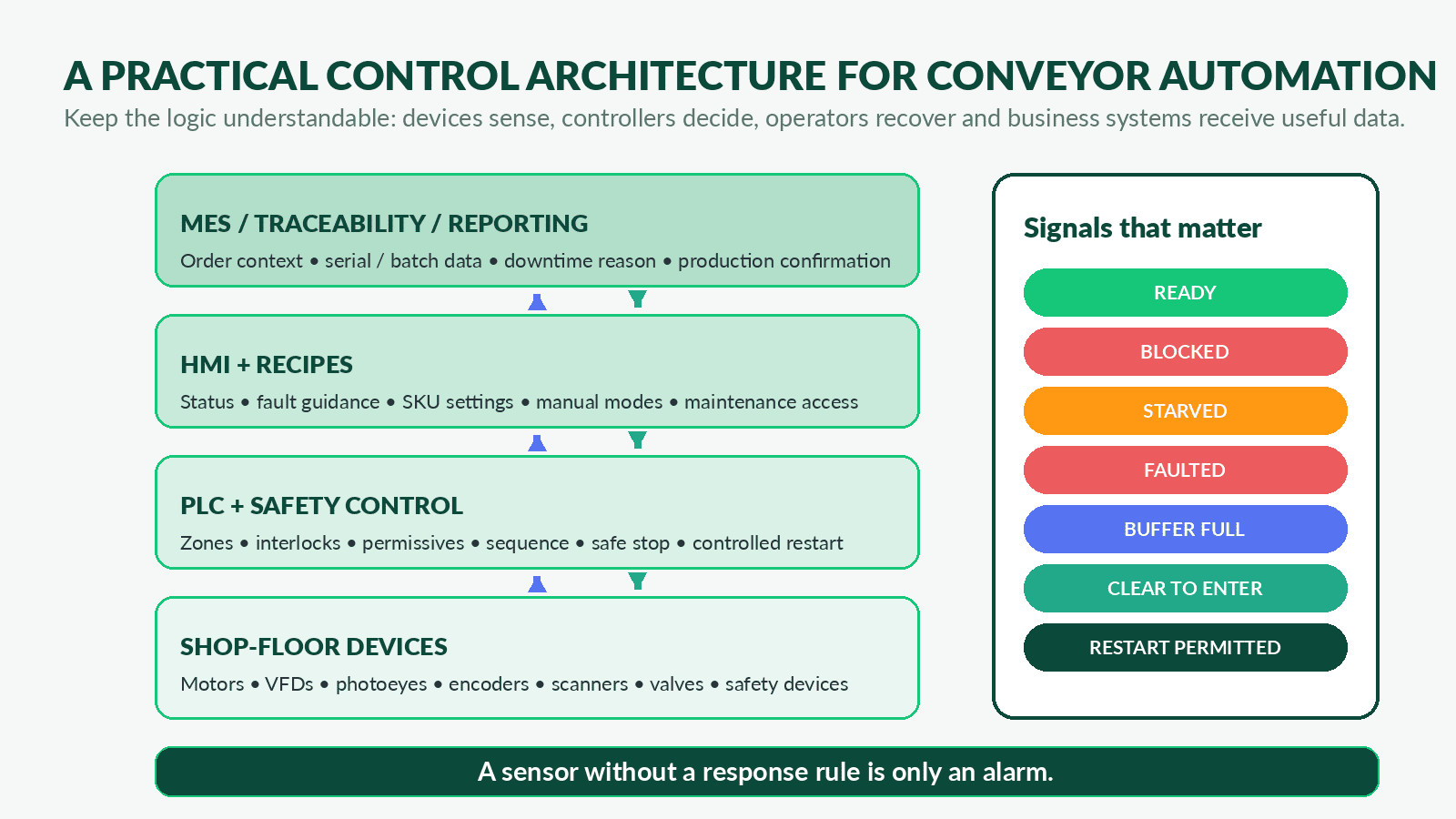
A practical conveyor automation architecture connects devices, PLC and safety control, operator interfaces and useful plant data.
Safety, Access, Isolation and Controlled Restart
A conveyor that reduces manual handling can still introduce nip, crush, entanglement, impact and unexpected-movement hazards. Safety is not a set of accessories added after the layout is finished. Risk assessment, guarding, access and control-system design must develop together for the actual tasks people perform.
Map routine production, replenishment, cleaning, jam clearing, inspection, setup, maintenance and fault recovery. Identify every place where a person may reach, enter, lean across, remove a guard or work near stored energy. Define how hazardous energy is isolated and how the system prevents unexpected start-up during servicing.
Emergency stops are important, but they are not a substitute for guarding or energy isolation. The design also needs a controlled restart philosophy. After an emergency stop, guard opening or power return, the line should not resume movement simply because the original run command is still present. The required checks, reset locations, warnings and restart permissions must be engineered and validated for the application.
Operational safety also includes visibility and recovery. Operators should understand which zone will move in manual mode, where a product may fall, how a full buffer is cleared and who controls the restart. A line that is technically safe but confusing during a fault will encourage hesitation and improvisation.
| Important note This article is a planning guide, not a site-specific compliance determination. Conveyor guarding, safety-related control functions, emergency stops, isolation and validation must be designed and reviewed by competent professionals using the standards and legal requirements applicable to the plant and application. |
A Practical Manufacturing Example: Machined Housings
Consider an illustrative plant producing machined aluminium housings. The process includes CNC machining, deburring, washing, visual inspection, dimensional checking, laser marking and packing. Today, operators move parts in plastic bins on trolleys. The trolleys are also used as temporary WIP storage, so the route and queue length change throughout the shift.
The visible complaint is labour spent walking. A short observation shows a larger problem. The washer frequently waits because the correct trolley has not arrived. Inspection becomes full after a gauge check or quality discussion. Failed parts are placed on a red table, but corrected parts sometimes re-enter without a clear sequence. When packing is busy, finished parts block the laser marker even though the machining cells could continue.
A practical concept could use a powered pallet or roller conveyor with defined carriers, a controlled buffer before washing, an inspection accumulation zone, a rework spur and a finished-product lane. Sensors confirm carrier presence. Each machine exchanges ready, blocked, fault and transfer-complete signals. The HMI shows where the flow is stopped and guides the permitted recovery sequence.
The project should not begin by buying the complete line. A pilot section between machining and washing can test carrier stability, transfer geometry, oil drainage, buffer logic and operator interaction. Representative good parts, rejected parts, empty carriers and worst-case loads should be included. Once the handoff is proven, the concept can expand to inspection and packing.
The expected benefits should be stated as measurable operating changes: fewer operator journeys, lower uncontrolled WIP, less starvation at washing, shorter recovery after inspection stops, clearer rework status and safer access. These are stronger acceptance criteria than simply confirming that the conveyor reaches its maximum speed.
KPIs to Capture Before and After Automation
| KPI | Why it matters |
| Good units per available hour | Measures useful output, not conveyor motion. |
| Blocked time by station | Shows where downstream capacity stops upstream flow. |
| Starved time by station | Shows where material or release logic fails to supply a process. |
| WIP positions and minutes | Reveals queue size and exposure to mix-up or damage. |
| Operator travel and handling touches | Shows whether repetitive movement was genuinely removed. |
| Fault recovery time | Measures how quickly the team returns to controlled production. |
| Reject and rework rate | Checks whether automation is protecting or damaging quality. |
| Changeover-to-first-good time | Measures repeatability across products or fixtures. |
| Unplanned stops by cause | Separates mechanical, control, product and process losses. |
| Maintenance response and repeat faults | Shows whether diagnostics and corrective action are effective. |
Ten-Step Manufacturing Conveyor Automation Roadmap
1. Define the pain in operational language
State the problem as walking, waiting, damage, unsafe handling, blocked machines, missed output or uncontrolled WIP. Avoid beginning with a preferred technology.
2. Observe real shifts
Study start-up, normal production, break coverage, changeovers, faults, cleaning, quality holds and shift end. One calm hour is not a representative process.
3. Build the baseline
Measure demand, cycle time, travel, WIP, starvation, blockage, rejects and recovery. Record the assumptions so benefits can be checked later.
4. Develop the flow concept
Select routes, conveyor surfaces, carrier strategy, buffers, bypasses, rework and operator access. Review it with the people who will operate and maintain it.
5. Review risk and access
Perform the required risk assessment. Define guarding, emergency stops, isolation, safe manual modes, access and restart philosophy before details are frozen.
6. Complete detailed engineering
Freeze mechanical layout, loads, interfaces, utilities, signal list, control narrative, recipes, safety functions, documentation and acceptance criteria.
7. Run a meaningful FAT
Test representative and worst-case products. Simulate full buffers, missing products, sensor failures, machine faults, emergency stops, power return and manual recovery.
8. Install with site readiness and rollback plans
Confirm floor, access, power, network, machine availability, shutdown sequence, contractor ownership, temporary production route and punch-list process.
9. Perform SAT and controlled ramp-up
Prove safe operation, product quality, rate, accumulation, interfaces, recovery, training and documentation. Ramp output in planned stages rather than forcing full rate immediately.
10. Sustain and improve
Review event data with operators and maintenance. Close repeat faults, manage software and mechanical changes, maintain spares and update procedures as the line evolves.
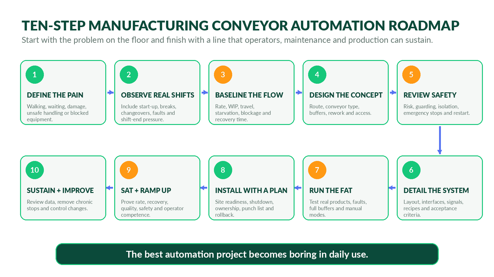
Ten-step manufacturing conveyor automation roadmap from problem definition to sustained improvement.
When Conveyor Automation Is Not the First Answer
A conveyor is not automatically the correct solution. If the product mix changes every week, the route is short and infrequent, the process itself is unstable or the true bottleneck is inside a machine, a fixed automated line may add cost without solving the loss.
Sometimes the first improvement is better workplace layout, standard containers, point-of-use material, a gravity rack, a lift table, a tugger route, a portable conveyor or a clearer quality decision. Low-cost changes can also provide the stable foundation needed for later automation.
Delay major automation when the product design is not frozen, the plant cannot provide maintenance ownership, the controls interfaces are unknown, or the business case depends on optimistic labour removal that operations does not intend to make. Automation should follow an honest operating model, not a spreadsheet assumption that nobody owns.
Common Manufacturing Conveyor Automation Mistakes
- Buying equipment before defining the process and exception routes.
- Using maximum conveyor speed as the main design target.
- Ignoring the smallest, least stable or most damaged product condition.
- Leaving transfer points and machine interfaces until late engineering.
- Adding buffers without defining full, release and recovery logic.
- Automating a workaround instead of correcting the process.
- Using sensors without a response rule or diagnostic purpose.
- Designing for normal flow but not reject, rework and hold conditions.
- Treating emergency stops as a complete safety strategy.
- Making manual recovery difficult or dependent on one expert.
- Collecting large amounts of data without ownership or review routines.
- Completing FAT with empty conveyors or only perfect products.
- Planning installation without a realistic shutdown and temporary-flow plan.
- Neglecting spares, documentation, backups and change control after handover.
Information to Share for an Accurate Automation Proposal
☐ Process flow from current source to final destination, including machines and manual stations.
☐ Product or carrier dimensions, weight, underside, centre of gravity and orientation.
☐ Smallest, largest, least stable and worst-condition products.
☐ Required good output, shift pattern, available production time and demand variation.
☐ Observed cycle times, blocked time, starved time, WIP and common interruptions.
☐ Existing layout drawings, elevations, photos and short operating videos.
☐ Upstream and downstream machine makes, models, interface points and available signals.
☐ Rework, reject, hold, inspection and bypass routes.
☐ Changeover requirements, product recipes and line-clearance rules.
☐ Traceability, barcode, RFID, weighing, vision or test-system requirements.
☐ Electrical supply, controls platform, network, plant standards and cybersecurity requirements.
☐ Environmental conditions, cleaning, temperature, dust, oil, moisture or corrosion exposure.
☐ Safety expectations, access requirements and plant-specific procedures.
☐ Installation window, production constraints, civil work and contractor responsibilities.
☐ FAT, SAT, performance, documentation, training, spares and support expectations.
☐ Future expansion, additional SKUs, lines, shifts or process equipment under consideration.
Frequently Asked Questions
What is manufacturing conveyor automation?
It is the coordinated movement and control of products, carriers or pallets between manufacturing processes using conveyors, sensors, drives, PLC logic, safety controls and machine interfaces. The goal is predictable material flow, not simply motorized transport.
Which conveyor types are commonly used in manufacturing plants?
Common choices include belt, powered roller, motor-driven roller, slat-chain, pallet, indexing, lift, cross-transfer and assembly-line conveyors. The product base, load, process, environment, route and control requirements determine the appropriate combination.
Where should a factory start with conveyor automation?
Start with a clearly observed operating problem and a baseline. Map the real material and exception flow, stabilize inconsistent work, identify the constraint and then select the lowest practical automation level that solves the problem.
Can an existing production line be automated in phases?
Yes. Many projects begin with a bottleneck, handoff or loading section and expand after the product, controls and recovery logic are proven. Phased design should still reserve space, I/O, panel capacity and software structure for planned growth.
How is conveyor capacity calculated for a production line?
Begin with required good output and available production time, then compare station cycle times, planned losses and recovery needs. The sustainable line rate is constrained by the slowest recoverable process, not the maximum speed of a conveyor section.
How much accumulation should a manufacturing line have?
There is no universal number. Buffer size should reflect product release rate, the interruption to be absorbed, allowable WIP, downstream recovery speed, product risk and available space. Express the design in both positions and minutes.
Can conveyors integrate with robots, CNC machines and test equipment?
Yes, when mechanical interfaces and control handshakes are defined. Typical signals include ready, blocked, faulted, product present, transfer request and transfer complete, plus identification or recipe data where required.
What should be included on the HMI?
Show meaningful line state, buffer condition, equipment status, fault location, guided recovery, recipe selection, permitted manual functions and maintenance diagnostics. Messages should be understandable to the people expected to act on them.
How should conveyor safety be planned?
Use a site- and task-specific risk assessment. Guarding, access, safety-related controls, emergency stops, energy isolation, manual modes and restart behaviour must be designed and validated for the actual application by competent professionals.
What data should a conveyor automation system collect?
Collect data linked to action, such as good output, blocked and starved time, fault cause, buffer full duration, reject reason, changeover recovery and repeated stops. Avoid collecting signals that nobody reviews or uses.
How should FAT and SAT be performed?
Test normal production and credible faults with representative and worst-case products. Include full buffers, missing products, rejected items, sensor failures, emergency stops, power return, manual recovery, machine interfaces and documented acceptance criteria.
What information does a conveyor manufacturer need for a quotation?
Provide product data, throughput, process flow, layout, machines, interfaces, buffers, exceptions, controls, environment, safety, installation constraints and acceptance requirements. Photos, drawings and videos improve proposal accuracy.
Conclusion: Automate the Handoffs, Not Just the Movement
The strongest manufacturing conveyor automation projects do not begin with a catalogue. They begin with a careful walk through the plant and an honest look at the minutes when production feels difficult: the missing carrier, the blocked machine, the full inspection bench, the rejected product with no route and the operator who knows a workaround that is not written anywhere.
A well-designed system turns those moments into defined states and manageable actions. Products have a clear route. Buffers have a purpose. Machines agree when transfer is allowed. Operators can see what stopped and recover without guessing. Maintenance can reach what must be serviced. Safety functions match the real tasks. Data points to losses that the team can actually remove.
The best result is not a conveyor that attracts attention. It is a production flow that feels calm, predictable and almost boring – even when something goes wrong.
| Discuss your manufacturing automation requirement Share your process flow, product details, target output, existing layout, bottlenecks and machine interfaces with Convello. A practical proposal can then be developed around the real material flow, safety, controls, installation and future expansion – not only the conveyor length. |