+91 99980 88430 | +91 95589 17778
 info@convello.in | sales@convello.in

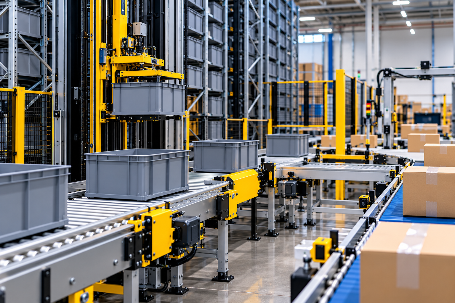
At 10:14 a.m., the automated storage crane retrieves the correct tote. The warehouse system shows the mission as successful. The tote reaches the end-of-aisle conveyor, but the goods-to-person station is not actually ready: an empty tote has not cleared the return lane, six other loads are already waiting, and the operator is resolving a quantity mismatch from the previous order.
On three screens, almost everything appears healthy. Physically, the tote has nowhere useful to go. The crane interface begins to fill, the next retrieval is delayed, and a technician is asked to investigate a problem that began outside the storage machine.
| The storage machine found the load. The operation had nowhere ready to receive it. This is an illustrative warehouse-floor composite, not a claimed Convello customer incident. It reflects a common integration lesson: AS/RS performance is determined by the complete handoff between storage, conveyors, buffers, workstations, software and people – not by crane or shuttle speed alone. |
What Is ASRS Conveyor Integration?
ASRS conveyor integration is the engineering of the physical and digital connection between an automated storage and retrieval system and the rest of a warehouse. The AS/RS may store pallets, totes, trays, cartons or small bins. Conveyors receive those loads, validate them, queue them, present them to storage, carry retrieved loads to people or machines, and move completed orders toward packing or dispatch.
The word integration matters because a conveyor cannot be treated as a neutral strip of equipment between two machines. It has to preserve load support, identity, sequence, availability and safe recovery. The design must answer five practical questions at every handoff:
- Is the physical load acceptable for the next machine or station?
- Is the destination genuinely ready, with enough space to receive it?
- Do the upstream and downstream controls agree on the transfer state?
- Can the load remain traceable if a read, transfer or communication fails?
- Can an operator or technician recover the load safely without corrupting inventory status?
Where AS/RS Integration Actually Happens
| Integration layer | What must be coordinated | Typical failure if ignored |
| Load and carrier | Dimensions, weight, base, pallet runners, tote quality, centre of gravity and identification | Load enters storage incorrectly, jams at a transfer, or cannot be handled by the extractor. |
| Mechanical interface | Conveyor height, support pattern, transfer gap, stops, lifts, turntables and alignment | A load is valid but does not transfer completely or arrives skewed. |
| Flow and buffer | Arrival rate, retrieval bursts, station capacity, queues, returns and recovery speed | The AS/RS is blocked by a full interface or workstations are starved. |
| Software and controls | WMS mission, WES/WCS orchestration, MFC routing, PLC states, identity and confirmation | The load is physically present but digitally unknown, duplicated or assigned to the wrong mission. |
| People and recovery | Access, HMI messages, manual modes, isolation, reconciliation and restart ownership | Operators improvise, reset repeatedly, or move a load without restoring system truth. |
The Complete Load Journey: More Than Storage In and Storage Out
A dependable AS/RS project begins by following the load from the first physical touch to the final dispatch confirmation. The storage machine is one important subsystem inside that longer journey.
1. Receiving and load identification
The operation must identify the pallet, tote, tray or carton and decide whether it is suitable for automation. This is where damaged pallets, missing tote bottoms, protruding wrap, mixed pallet footprints and unreadable labels should be captured – before they enter a tightly controlled storage aisle.
2. Profile checking and quality gates
Unit-load systems commonly need dimensional, weight and overhang checks. Mini-load systems need tote or carton quality checks, minimum base dimensions and reliable barcode or RFID reads. A profile check is not a ceremonial sensor frame; it is the boundary that protects the AS/RS from loads it was not designed to handle.
3. Inbound buffering and sequencing
The inbound conveyor should hold enough loads to absorb receiving bursts and let software sequence storage missions. It also needs a defined path for rejected loads. A failed profile check should not stop the entire receiving route or leave the rejected load occupying the only interface position.
4. Storage interface
At the I/O station, the conveyor and storage equipment exchange readiness and transfer confirmation. The load must be fully positioned, positively detected and associated with the correct mission before the crane, shuttle or robot accepts it.
5. Retrieval and outbound buffering
A storage system may release loads in bursts even when picking demand is relatively smooth. Outbound buffering converts those bursts into a usable sequence for goods-to-person stations, decanting, replenishment, inspection or production supply.
6. Picking, processing and order consolidation
The conveyor must present loads at an ergonomic and repeatable position, then manage residual inventory, completed order containers, empty carriers and exceptions. If an operator cannot finish a task, the system needs a defined hold or recovery state rather than an informal trolley beside the station.
7. Packing, palletising and dispatch
After picking, the system may route order totes to packing, cartons to sortation, or completed pallets to wrapping and shipping. The outbound route must protect order identity and destination status just as carefully as the storage interface protects inventory identity.
8. Empty-carrier and exception return
Empty totes, trays and pallets are part of the capacity model. So are no-reads, damaged loads, quantity mismatches and incomplete transfers. If these flows are not designed, they become the workarounds that slowly consume the aisle and workstation space the automation was meant to save.
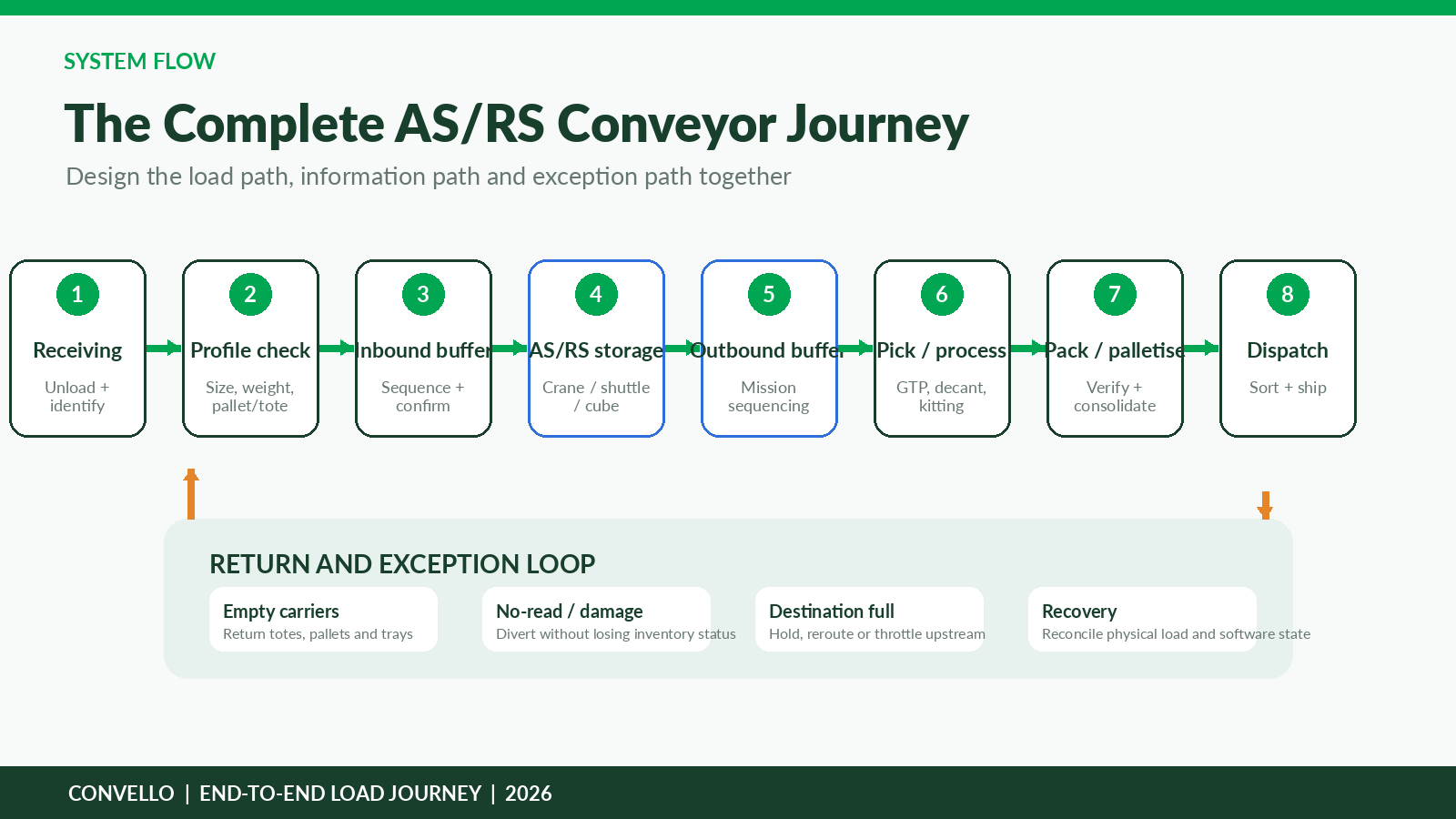
Figure 1. The useful system boundary runs from receiving to dispatch and includes the return and exception loop.
Handoff Review Questions
| Ask at every interface | Evidence to confirm |
| Is the correct load fully present? | Presence sensors, position stop and verified identity. |
| Is the destination genuinely ready? | Free position, reserved capacity and no blocked downstream route. |
| Who owns the load during transfer? | Agreed source, destination and incomplete-transfer states. |
| How is an exception recovered? | Safe access, reconciliation, authorised restart and mission closeout. |
AS/RS Types and the Conveyor Interfaces They Need
The correct interface depends on the stored load and the storage technology. A conveyor designed for rigid totes is not automatically suitable for full pallets, and a pallet conveyor cannot be scaled down by changing only its width.
Unit-load or pallet AS/RS
Unit-load systems store full pallets, stillages or other heavy unit loads. Their interfaces commonly use powered pallet rollers or chain conveyors, pallet stops, turntables, cross transfers, lifts and profile-check stations. Pallet runner direction, underside damage, load overhang, wrap condition and accumulated section load are central design inputs.
Mini-load AS/RS
Mini-load systems handle totes, trays, cartons and storage pans. Interfaces may use 24 V powered roller conveyor, belt conveyor, vertical lifts, merges, diverts and goods-to-person loops. The smallest accepted load, flexible bases, tote lip geometry, sensor visibility and queue length often matter more than the maximum load.
Shuttle and cube-based systems
Shuttle and cube systems usually connect through ports, lifts and short conveyor loops. Their storage capacity can be very high, but workstation throughput may be limited by port availability, lift cycles, robot or shuttle balance, tote presentation time and empty-bin supply.
Vertical lift and micro-load systems
Vertical lift modules and compact small-parts systems often use short indexing conveyors or assisted workstations rather than a large conveyor network. The engineering focus moves toward presentation height, confirmation, order sequence and safe operator access.
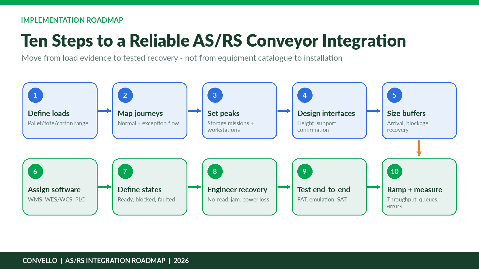
Figure 2. Match the conveyor interface to the load carrier and storage mechanism, not to a generic automation label.
| Convello application fit Convello currently positions its pallet conveyors for automated workflow, bidirectional transfer, accumulation and AS/RS compatibility. Its roller conveyors can connect with lifts, cross transfers, scanners and PLC-controlled zones. These capabilities can form the transport and interface layer around an AS/RS when the load, flow, controls and safety requirements are engineered together. |
Fifteen Design Decisions That Determine Whether the Integration Works
1. Define the worst accepted load, not only the perfect sample
Record minimum and maximum dimensions, weight, base stiffness, pallet runner direction, overhang, wrap, label location, centre of gravity and condition limits. Test a worn but acceptable tote and a less-than-perfect pallet. The AS/RS should not discover your packaging variation after go-live.
2. Standardise carriers before adding precision automation
Mixed pallet types, bowed tote bases and damaged trays create uncertainty at extractors, transfer points and sensors. If carriers cannot be standardised, the project may need pallet changers, adaptors, segregation rules or a dedicated rejection route.
3. Size every I/O station as a process, not a single position
An I/O station needs approach space, positive positioning, identity confirmation, transfer clearance and a recovery position. If one load blocks the interface, can the system continue through another station, or does one fault stop the entire aisle?
4. Separate average, sustained peak and short-burst demand
Daily totals hide the moments that create queues. Measure receiving waves, replenishment periods, order-release peaks, shift changes and carrier cutoffs. The useful capacity is the rate the complete system can sustain while maintaining correct sequence and acceptable recovery – not the highest speed of one device.
5. Size buffers from interruption and recovery, not from available floor length
A buffer should protect a known process interruption. Calculate how many loads arrive during the interruption, then check whether the downstream process can clear that backlog after restart. A longer conveyor can postpone a problem without solving it.
6. Protect sequence where sequence matters
Some storage missions can be resequenced freely; others cannot. Production kits, wave-picked orders, store routes and pallet-building sequences may need strict order. The WES or WCS should know when it can optimise travel and when it must preserve sequence through the conveyor network.
7. Treat the workstation as part of the automation
A fast AS/RS can still underperform if the workstation forces excessive reaching, searching or confirmation. Presentation height, screen position, lighting, replenishment, reject handling and empty-carrier removal influence the rate at which the conveyor can release the next load.
8. Engineer the return flow at the same time as the outbound flow
Empty totes and residual inventory need a reliable path back. If they share conveyor sections with completed orders, define priority and blocking logic. If operators must manually nest, inspect or close carriers, include those cycle times in the capacity model.
| Evidence to collect | Why it matters |
| Load drawings and real samples | Confirms support, transfer, sensor and extractor compatibility. |
| Hourly arrival and retrieval profiles | Reveals peaks and burst behaviour hidden by daily averages. |
| Workstation cycle-time distribution | Shows normal variation, not only the best observed cycle. |
| Interruption duration and frequency | Provides an engineering basis for buffer capacity. |
| Exception and return volume | Prevents rejected or empty carriers from consuming normal flow capacity. |
| Recovery rate after restart | Determines whether the system can actually clear a queue. |
Design Decisions 9-15: Identity, Controls, Recovery and Growth
9. Give every exception a physical destination and a digital state
No-read, overweight, damaged, wrong-profile, quantity-mismatch and unknown-load conditions should not share one vague reject lane. The system must know why the load was diverted, who owns it, and what must be confirmed before it re-enters normal flow.
10. Assign clear responsibilities to WMS, WES/WCS, MFC and PLC
The WMS usually owns inventory and order intent. A WES or WCS may sequence work and manage subsystem inventory. Material-flow control routes real-time missions, while PLCs execute machine states and interlocks. Names vary by solution, but responsibility cannot remain ambiguous.
11. Define the transfer handshake before writing code
A robust transfer typically confirms source load present, source ready, destination available, transfer permission, movement active, destination load present, source clear, identity verified and mission complete. Timeouts and partial states need defined behaviour.
12. Plan for the load that stops halfway
A partial transfer is more complicated than a clean stop. Two sensors may see the load, neither machine may claim it, and software may not know which location is authoritative. The recovery procedure should reconcile physical position and inventory state before motion resumes.
| A load cannot be physically on the conveyor and digitally nowhere. Recovery is complete only when the load is safely positioned, its identity and location are reconciled, the blocked mission is resolved, and the restart path is deliberately confirmed. |
13. Define power-loss and communication-loss recovery
After power returns, conveyors may still contain loads between zones and storage equipment may have unfinished missions. The system should re-establish sensor states, load identity, destination availability and machine ownership before automatic movement restarts.
14. Provide safe manual recovery and maintenance access
Technicians need access to stops, drives, sensors, transfer mechanisms and I/O positions. Operators need a controlled way to remove or reintroduce a load. Guarding, isolation, interlocks and manual modes must support the actual recovery task rather than forcing people to improvise around the equipment.
15. Reserve mechanical, electrical and software capacity for growth
Future growth may require another workstation, a new dispatch lane, more shuttles, a second crane interface or a different load carrier. Reserve panel capacity, network addresses, PLC memory, physical connection points, conveyor space and software licences before expansion becomes urgent.
Example Machine Handoff States
| State | Meaning | Expected action |
| Ready | Interface clear and able to receive or release the next load. | Permit mission only when adjacent subsystem also reports ready. |
| Occupied | A verified load is positioned at the interface. | Maintain identity and wait for destination permission. |
| Blocked | Destination lacks space or is unavailable. | Hold upstream release and display the reason. |
| Transfer active | Load is moving between owners. | Monitor time, position and confirmation sensors. |
| Transfer incomplete | Expected confirmation did not occur. | Stop movement, protect the load and enter controlled recovery. |
| Identity uncertain | Physical presence and digital record do not agree. | Divert or reconcile before normal routing. |
| Safe stop | Movement is inhibited by a safety condition. | Do not treat reset as permission to restart automatically. |
Concept-Stage Calculations for AS/RS Conveyor Interfaces
Calculations should be based on the complete system, not on the nominal speed of a crane, shuttle or conveyor. The following formulas are useful for early planning and must be validated using actual load samples, controls, equipment data and operating rules.
| Release interval | Release interval (seconds/load) = 3,600 ÷ peak loads per hour A demand of 600 tote presentations per hour requires an average release every 6 seconds. |
| Initial conveyor speed | Speed (m/min) = product pitch (m) × loads per minute At a 1.1 m pitch and 10 loads per minute, the initial transport speed is 11 m/min before allowances for transfer and control behaviour. |
| Queue growth | Queue growth = max(0, arrival rate – downstream rate) × interruption time Use consistent time units. Include loads already in transfer and any storage missions that cannot be cancelled. |
| Recovery time | Recovery time = backlog ÷ (recovery capacity – continuing arrival rate) If the downstream process cannot run faster than the continuing arrival rate, the backlog will not clear. |
Illustrative Indian Project: Mini-Load AS/RS for Industrial Spare Parts
Consider a proposed distribution centre handling small industrial spares in standard totes. The concept includes a 12,000-tote mini-load AS/RS, four goods-to-person workstations, two inbound decant stations, an exception bench and a conveyor loop connecting storage, picking, packing and empty-tote return. This is an illustrative engineering example, not a claimed Convello installation.
| Planning input | Illustrative value | Design implication |
| Peak AS/RS tote presentations | 600 totes/hour | Average interface release every 6 seconds. |
| Four GTP stations | 135 totes/hour per station | Combined planned station demand of 540 totes/hour. |
| Headroom for imbalance and exceptions | 60 totes/hour | Protects against uneven station demand and rework. |
| Illustrative tote pitch | 1.1 m | Initial conveyor transport speed of 11 m/min at 600 totes/hour. |
| Typical station interruption | 90 seconds | Approximately 3.4 tote arrivals at 135 totes/hour. |
| Initial station buffer target | 6 tote positions | Adds practical allowance for one tote in transfer and cycle variation. |
| Illustrative recovery capacity | 195 totes/hour per station | Net recovery of 60 totes/hour above continuing demand; six-tote queue clears in about six minutes. |
The calculation shows why the fastest machine should not release work blindly. If two stations stop together, or if empty totes block the return route, the shared outbound loop can fill before the storage machine reports a fault. The WCS should therefore use station availability, interface occupancy and buffer thresholds when releasing retrieval missions.
A practical project review would also test:
- Whether the smallest tote remains supported across every transfer and lift.
- Whether a tote can be routed around a stopped workstation without breaking order sequence.
- How no-read totes are identified and reconciled.
- Whether four stations can be supplied fairly when one order wave dominates demand.
- How empty totes are returned when the normal return conveyor is unavailable.
- Whether a load remains traceable through power loss, manual recovery and restart.
Verified Public Projects: Integration in Real Operations
| Case-study disclosure The following examples are external public industry projects published by Dematic and Interroll. They are included for engineering learning and must not be presented as Convello installations, customer results or guaranteed outcomes. |
Dot Foods: AS/RS, Conveyor Queues and Goods-to-Person Workstations
Dematic describes a freezer automation project for Dot Foods that replaced a manual planned-item-retrieval process for low-quantity SKUs. The system uses WMS requests to retrieve inventory automatically and convey it to a central picking area. Published specifications include 6,552 storage bins, 90,000 cubic feet of storage, 120 bins processed per hour and four operator workstations. Roller conveyor connects the AS/RS to the workstations, with up to six storage pans queued in front of each station, while pallet conveyor carries picked orders toward shipping. [1]
The important lesson is not one individual number. The storage machines, end-of-aisle conveyor interfaces, station queues, workstations, WMS/WCS and shipping route were treated as one flow. The six-pan queues are especially instructive: they protect continuous work at the station while the storage and transport systems complete the next missions. They also create a visible capacity limit that software can manage.
Café Amazon: Storage, Conveyor, Vertical Movement, Robotics and Sortation
Interroll describes a Café Amazon distribution operation in Thailand that combines automated storage, conveyor transport, vertical lifts, robots and crossbelt sortation. The public project summary cites an AS/RS serving as primary storage for 25,000 pallets, six robots feeding a crossbelt sorter and sorter capacity above 7,200 boxes per hour. [2]
This project demonstrates a different scale of integration. The AS/RS is not the final destination; it feeds an end-to-end network that must pick, convey, store and sort. Storage capacity can be impressive, but order throughput depends on whether lifts, robots, conveyor merges, destination lanes and sortation remain balanced.
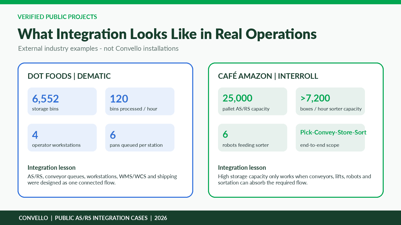
Figure 3. Public project figures illustrate how storage, conveyor, workstations and downstream automation must be capacity-matched.
What These Projects Suggest for a New AS/RS Conveyor Project
- Design buffers at workstations and interfaces around measured interruptions, not arbitrary conveyor length.
- Use software to release missions based on real destination capacity, not only storage availability.
- Treat vertical movement, sortation and packing as part of the same throughput model.
- Provide enough diagnostic information to distinguish storage, conveyor, workstation and software causes.
- Plan maintenance and recovery so one failed interface does not trap the entire storage subsystem.
Software and Control Architecture: Who Owns the Load?
An automated warehouse runs on several software and control layers. The product names vary, but the project needs a clear answer to one question at every moment: who owns the next decision for this load?
| Layer | Typical responsibility | Questions to resolve |
| ERP / host | Commercial orders, purchasing, production demand and enterprise records. | What demand is released to the warehouse and when? |
| WMS | Inventory location, order allocation, replenishment and business rules. | Which SKU or pallet is required, and what inventory transaction is expected? |
| WES / WCS | Work sequencing, subsystem orchestration, dynamic routing and visibility. | Which mission should run next, and which station can accept it? |
| MFC / equipment controller | Real-time material-flow routing and equipment task coordination. | Which physical path and interface will move the load? |
| AS/RS controller | Crane, shuttle or robot missions and storage location execution. | Is the storage equipment able to store or retrieve the assigned load? |
| Conveyor PLC | Zones, motors, transfers, sensors, queues, interlocks and handshakes. | Is the route clear, and did the physical transfer complete? |
| Safety control | Safe stopping, access, guarding and monitored restart conditions. | Is movement permitted from a safety perspective? |
| HMI / SCADA | Operator visibility, alarms, modes, trends and recovery guidance. | What happened first, where is the load, and what action is required? |
Swisslog describes modern automated warehouses as software stacks that may include WMS, WES, WCS, MFC, SCADA and PLC layers. It also notes that execution software can continuously track subsystem inventory while PLC and controls software connect the software layer to conveyors, robots and machines. [3]
A Practical Transfer Handshake
- Source confirms the correct load is fully positioned.
- Destination confirms that it is available and has reserved capacity.
- Source requests transfer and destination grants permission.
- Movement begins; both systems monitor timeout and safety conditions.
- Destination confirms the load is fully received.
- Source confirms that its interface is clear.
- Identity and mission status are updated before the next load is released.
Good HMI messages should identify the first failed condition. “ASRS fault” or “Zone timeout” is rarely enough. A more useful message might state: “Outbound interface 2 occupied; tote 004817 awaiting GTP station 3; station buffer full; operator action required at empty-tote return.”
End-to-End Tests Before Go-Live
| Test scenario | Expected system behaviour |
| Wrong pallet or tote profile | Reject before storage entry; retain identity and reason. |
| Unreadable barcode / RFID | Divert to controlled exception and prevent anonymous storage. |
| Destination buffer full | Stop or reroute retrieval release before the storage interface blocks. |
| Sensor stuck on or off | Detect inconsistency, stop the affected route and show the first-out fault. |
| Crane or shuttle unavailable | Protect active loads and use alternate aisle or controlled hold if designed. |
| Conveyor jam | Stop upstream release, retain queue identity and provide safe recovery instructions. |
| Partial transfer | Freeze ownership, reconcile physical position and prevent duplicate movement. |
| Duplicate or unexpected identity | Quarantine the load and protect inventory accuracy. |
| Power loss with loads in zones | Rebuild occupancy and ownership before automatic restart. |
| Network or host communication loss | Complete or hold safe local actions according to agreed rules. |
| Emergency stop / access gate | Enter a safe state; require deliberate reset and restart confirmation. |
| Manual load removal / re-entry | Reconcile the load before it returns to normal flow. |
A Ten-Step AS/RS Conveyor Integration Roadmap
Figure 4. Reliable integration starts with load evidence and finishes with measured, recoverable operation.
1. Define the load family and rejection limits.
Create a controlled specification for pallets, totes, trays or cartons, supported by real samples and clear rejection criteria.
2. Map normal, return and exception journeys.
Draw every physical and digital route, including empty carriers, no-reads, damage, quality holds and manual recovery.
3. Establish average, sustained peak and burst requirements.
Use hourly and minute-level profiles. Separate storage missions from workstation presentations, replenishment and returns.
4. Engineer each mechanical interface.
Confirm height, support, transfer gap, alignment, stops, presence sensing, identity and maintenance access.
5. Size buffers and recovery capacity.
Calculate queue growth during interruptions and how quickly the downstream process can clear the backlog.
6. Assign software and controls responsibility.
Write an interface-control document showing who creates, routes, executes, confirms and closes each mission.
7. Define states, alarms and operator ownership.
Use clear states such as ready, occupied, blocked, transfer active, incomplete, identity uncertain and safe stop.
8. Engineer recovery before commissioning.
Write procedures for no-reads, partial transfers, jams, power loss, communication loss and manual load removal.
9. Test end-to-end through FAT, emulation and SAT.
Test failure conditions and recovery as seriously as normal throughput. Use actual load samples and realistic destination blocking.
10. Ramp gradually and measure the complete system.
Increase volume in controlled stages. Track queues, blocked time, mission latency, no-reads, interface faults and time to recover.
KPIs That Reveal Integration Quality
- AS/RS I/O station availability and blocked time
- Loads presented per hour by station and by shift
- Average and maximum buffer occupancy
- Mission request-to-presentation time
- No-read, wrong-profile and exception rate
- Partial-transfer and repeated-reset frequency
- Time to diagnose and safely recover a fault
- Inventory reconciliation adjustments after recovery
- Percentage of planned peak sustained without manual workarounds
When AS/RS May Not Be the Right First Investment
AS/RS can provide high density and repeatable flow, but it is not a universal answer. A simpler solution may be better when volumes are low, load carriers are uncontrolled, inventory data is unreliable, the building cannot support the required structure, processes change weekly, or most movements are irregular exceptions. Process stabilisation, carrier standardisation, targeted conveyors, AMRs or selective automation may deliver a better first step.
Common AS/RS Conveyor Integration Mistakes
| Mistake | Why it causes trouble | Better approach |
| Buying storage capacity before mapping outbound work | Workstations and dispatch become the real bottleneck. | Model the complete load journey and sustained peak. |
| Using only average hourly volume | Short bursts fill interfaces and create crane blocking. | Measure minute-level peaks, waves and interruptions. |
| Ignoring damaged or mixed carriers | Mechanical reliability depends on predictable load geometry. | Standardise, inspect and reject before storage entry. |
| Treating buffers as spare conveyor length | The queue may never clear after restart. | Size from arrival, interruption and recovery rates. |
| No physical route for exceptions | Unknown or damaged loads occupy normal flow space. | Provide controlled exception destinations and ownership. |
| Unclear WMS/WCS/PLC responsibilities | Missions remain open or loads lose digital ownership. | Create an interface-control and state document. |
| Generic HMI alarms | Operators reset symptoms without finding the first cause. | Show location, load ID, failed condition and required action. |
| Testing only normal flow | Go-live becomes the first full test of faults and recovery. | Test blocked destinations, no-reads, power loss and partial transfers. |
| Manual recovery without reconciliation | Physical and digital inventory diverge. | Require authorised load-location confirmation before restart. |
| No expansion allowance | A new station or aisle requires major controls and layout rework. | Reserve mechanical, electrical, network and software capacity. |
Information to Share Before Requesting an AS/RS Conveyor Quote
- Business objective, current process and measurable problem to solve.
- Building drawings, clear height, columns, floors, fire strategy interfaces and available expansion area.
- Load-carrier drawings, minimum and maximum dimensions, weight, base, runner direction, condition limits and real samples.
- SKU count, inventory profile, dwell time and growth assumptions.
- Inbound, retrieval, replenishment, return and exception volumes by hour and peak period.
- Required storage capacity, throughput, availability and recovery expectations.
- Workstation count, task cycle times, operator roles and ergonomic requirements.
- Receiving, profile-check, packing, sortation, palletising and dispatch interfaces.
- WMS/ERP environment, required WES/WCS/MFC integration and software ownership model.
- PLC, network, cybersecurity, HMI, SCADA, data and reporting requirements.
- Expected manual, maintenance and emergency operating modes.
- Guarding, access, isolation, site standards and risk-assessment requirements.
- Installation phasing, shutdown windows, FAT/SAT expectations and production ramp plan.
- Documentation, source code, backups, training, spare parts and lifecycle support expectations.
Frequently Asked Questions
1. What is ASRS conveyor integration?
It is the mechanical, flow and control connection between automated storage equipment and receiving, picking, processing, packing or dispatch. It includes conveyors, I/O stations, buffers, sensors, load identification, software handshakes, exceptions and safe recovery.
2. Which conveyors are used with pallet AS/RS?
Powered pallet roller or chain conveyors are common, often combined with stops, turntables, chain transfers, profile checks, lifts and accumulation. Pallet base, runner direction, maximum weight and load condition determine the final design.
3. Which conveyors are used with mini-load AS/RS?
Mini-load systems commonly connect through 24 V powered roller conveyor, belt conveyor, lifts, merges, diverts and goods-to-person loops for totes, cartons, trays or storage pans.
4. How much buffer is needed at an AS/RS interface?
Buffer capacity should be calculated from the arrival rate, expected interruption duration, loads already in transfer and downstream recovery capacity. Available floor length alone is not an engineering basis.
5. What is an AS/RS I/O station?
An input/output station is the controlled interface where a load is presented to or received from the storage equipment. It normally confirms position, presence, identity, readiness and transfer completion.
6. How do WMS and WCS work with an AS/RS?
The WMS generally manages inventory and order intent. The WES or WCS sequences and orchestrates work, while material-flow control and PLCs route and move loads through conveyors and storage equipment. Exact responsibilities must be agreed for the project.
7. Why can an AS/RS be fast while the warehouse remains slow?
Storage throughput may be limited by workstation cycle time, conveyor queues, vertical lifts, sortation, packing, destination availability, exception handling or recovery. The complete system sets the useful throughput.
8. How are damaged pallets or totes handled?
They should be detected at receiving or profile checking and diverted to a controlled exception area. The reason, load identity, owner and re-entry method should remain visible in the software.
9. What happens if a load stops halfway between the conveyor and AS/RS?
Movement should stop, ownership should be frozen, and the load position should be reconciled using sensors and authorised inspection. The mission should not resume until physical and digital location agree.
10. Can AS/RS conveyors integrate with existing warehouse equipment?
Yes, provided interface heights, load standards, throughput, controls, safety, network communication and recovery procedures are compatible. Retrofits often require more detailed survey and phased testing.
11. What should be tested during AS/RS conveyor commissioning?
Test normal flow plus wrong profile, no-read, full destination, sensor failure, jam, partial transfer, duplicate identity, crane unavailable, power loss, communication loss, emergency stop and manual recovery.
12. When is AS/RS not the right solution?
It may not be the best first investment when load carriers are uncontrolled, volume is low, processes change constantly, inventory data is unreliable, the building is unsuitable or simpler automation can solve the main problem.