+91 99980 88430 | +91 95589 17778
 info@convello.in | sales@convello.in

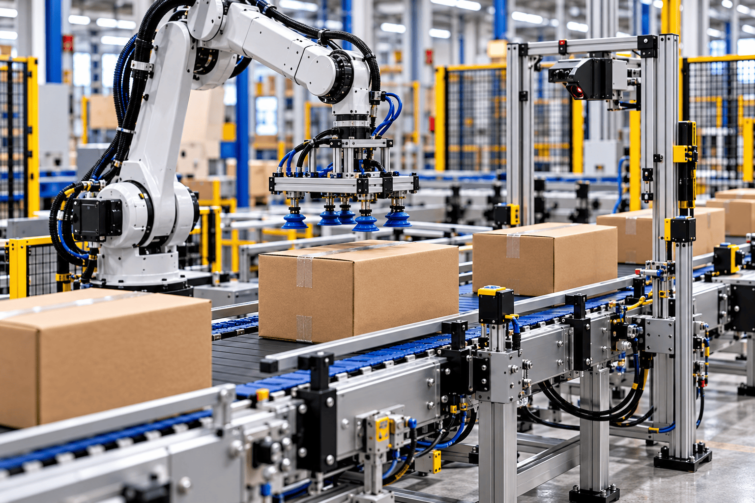
At 11:18 a.m., a carton reaches the robot cell slightly out of square. The robot has no fault. The conveyor is running. The vision system can see the label. Yet the vacuum cup lands too close to a taped flap, so the pick is rejected.
An operator straightens the carton and presses reset. The cell works again – until another carton arrives with a softened corner. By the end of the shift, the robot has repeated its programmed motion perfectly, but people have corrected the product presentation fourteen times.
| PRACTICAL RULE The robot is accurate. Product presentation, timing and recovery must be equally repeatable. |
This opening is an illustrative plant-floor composite, not a claimed Convello customer incident. It reflects a common integration mistake: treating the robot as the complete automation project while the conveyor, packaging, gripper, sensors, controls, safety and operator workflow are designed separately.
What Is Robotic Conveyor Integration?
Robotic conveyor integration is the engineering process that makes a conveyor and robot operate as one coordinated production cell. The conveyor presents the product. Sensors, encoders or vision describe its location. The robot picks or processes it. The control system manages permission, timing, faults and downstream availability. The safety system controls how people may enter, replenish, clear, inspect and restart the cell.
The robot may be an industrial six-axis arm, delta robot, SCARA robot, gantry system or collaborative robot. The conveyor may be belt, roller, slat chain, pallet, indexed, continuously moving or a short presentation section. What matters is not the equipment name but whether the complete system can answer five questions reliably:
- Where is the product?
- Is it stable and suitable to grip?
- Is the robot allowed and able to act?
- Is the destination ready?
- What happens when the normal cycle fails?
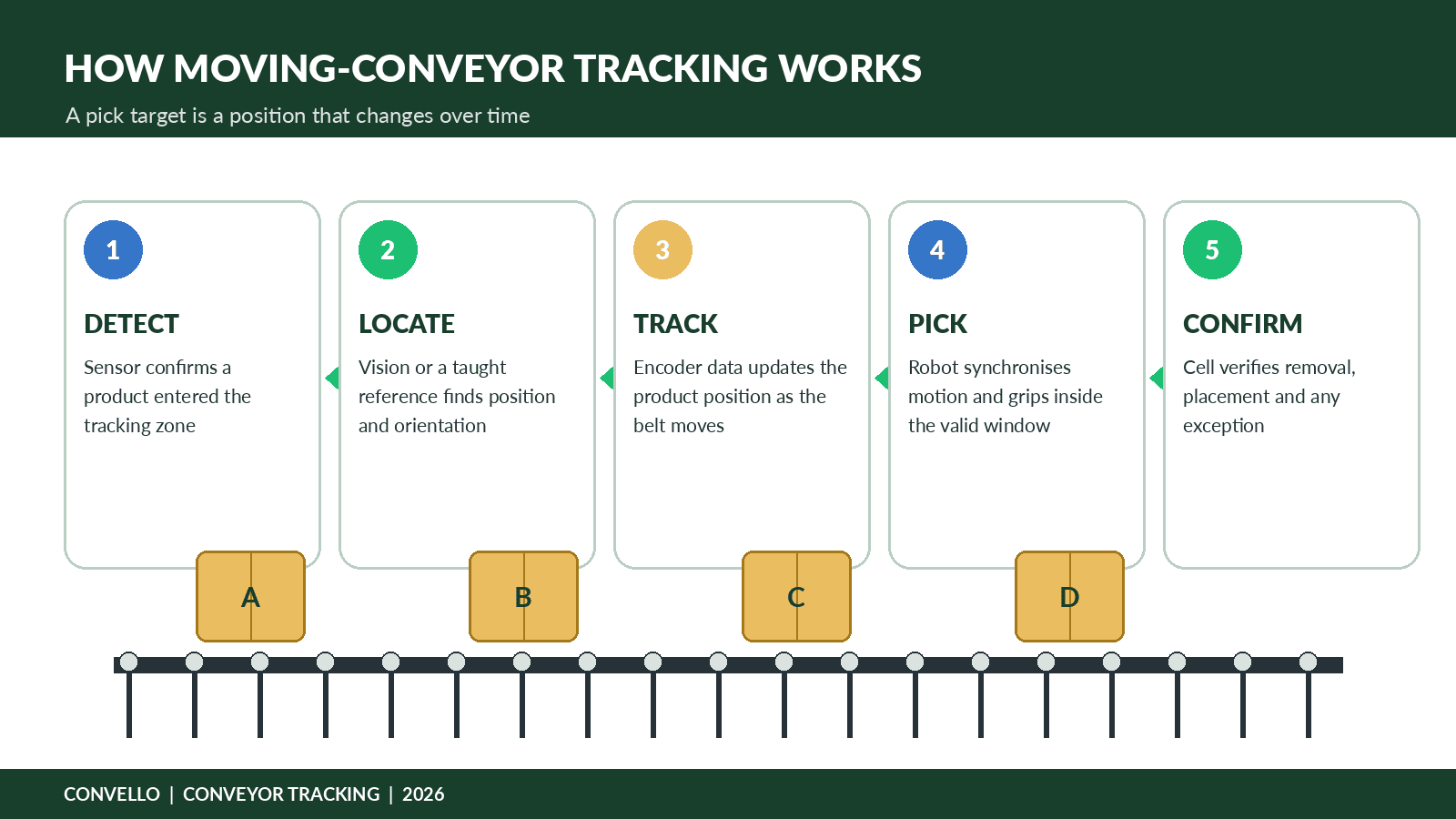
Figure 1. Moving-conveyor tracking converts product detection, position and belt movement into a time-dependent robot pick target.
Where Robots and Conveyors Work Together
| Application | Conveyor role | Robot role | Design focus |
| High-speed pick and place | Spaces and presents loose products | Picks, groups or packs products | Spacing, orientation, lighting and missed-pick handling |
| End-of-line palletising | Feeds cases or bags and buffers interruptions | Builds the pallet pattern | Carton quality, gripper, pallet change and buffer capacity |
| Machine tending | Moves fixtures, trays or parts between processes | Loads and unloads machines | Datum repeatability, process handshake and rejected parts |
| Assembly and inspection | Positions a carrier or stops it at a station | Assembles, tests or inspects | Fixture accuracy, station access and result traceability |
| Sorting and rework | Presents identified products and routes exceptions | Moves the product to the correct destination | Identification confidence and destination-full logic |
| Depalletising | Receives empty pallets or outgoing products | Removes cases, bags or layers | Unstable loads, damaged packs and layer variation |
A useful starting question is not, “Which robot should we buy?” It is, “What condition must the product be in when the robot needs to act?” That question exposes whether the line needs singulation, side guides, a squaring stop, a fixture, an encoder, a vision station, a reject lane, a buffer or a different conveyor surface.
Five Common Robot-Conveyor Architectures
- Indexed stop-and-pick: The conveyor stops the product at a repeatable datum before the robot acts. It is simple to understand and can be robust, but every index consumes time and may limit output.
- Continuous conveyor tracking: The conveyor keeps moving while an encoder and vision or sensor reference update the product position. It suits higher rates but requires disciplined calibration, timing and product spacing.
- Buffered presentation: Products accumulate or queue before a controlled release point. The robot receives one product, one group or one carrier at a time. This separates irregular upstream flow from the robot cycle.
- Fixture or pallet transfer: The conveyor moves a known carrier, fixture or pallet into a robot station. The fixture creates a stable datum for assembly, inspection, loading or unloading.
- End-of-line palletising cell: A case, bag or tray conveyor feeds a robot that builds a pallet. The cell also needs full-pallet removal, empty-pallet supply, slip-sheet handling, buffer logic and a safe operator route.
How Conveyor Tracking Works
Conveyor tracking is more than placing a camera over a belt. The robot must know where the product was detected, how fast and in what direction the conveyor is moving, how long the information takes to travel through the controls, and whether the target will remain inside the robot work envelope long enough to complete the pick.
| Stage | What the system must know |
| Detect | A photo-eye, trigger or vision event confirms that a product has entered the tracking zone. |
| Locate | Vision, a taught fixture datum or product sensor determines position and, where required, orientation. |
| Track | An encoder or servo reference updates the product position as the conveyor moves. |
| Reserve | The robot controller or cell software assigns the target to a robot and checks whether it remains pickable. |
| Pick and confirm | The robot synchronises its motion, grips the product and confirms whether removal and placement succeeded. |
Common failures include encoder slip, camera movement, inconsistent conveyor speed, changing belt stretch, poor lighting, product overlap, inaccurate trigger distance and a pickup zone that is too short for the required cycle. A line-tracking package can simplify the software, but it cannot correct unstable packaging or an unsuitable conveyor layout.
FANUC describes line tracking that combines vision, queue management and moving-conveyor picking; the exact achievable rate depends on the selected robots, product and cell design. View source
Choose the Robot Around the Task – Not the Brand
| Robot type | Typical strength | Common conveyor use | Important limitation |
| Delta | Very fast movement of light products over a conveyor | Food packs, confectionery, small packages | Payload, reach and product spacing |
| SCARA | Fast planar motion and vertical insertion | Small parts, kitting, assembly, tray transfer | Limited orientation flexibility compared with six-axis robots |
| Six-axis industrial robot | Flexible reach and orientation across a larger cell | Machine tending, packing, palletising, assembly | Guarding, reach envelope, cycle path and floor space |
| Collaborative robot | Flexible automation where people need planned access | Low-to-medium rate tending, palletising and repetitive handling | The complete application still requires a risk assessment |
| Gantry or Cartesian | Long rectangular travel and regular motion | Heavy parts, layer handling and multi-station transfer | Structure, installation height and changeover flexibility |
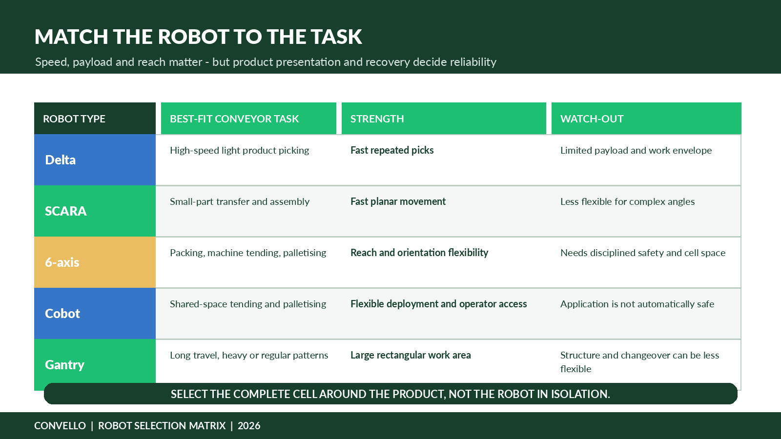
Figure 2. Robot selection should follow the product, task, reach, payload, rate, changeover and recovery requirement.
Fifteen Design Decisions That Determine Reliability
- Define the complete product range. Record the smallest, largest, lightest, heaviest and least stable accepted product. Include packaging variation, damaged-but-acceptable conditions, raised flaps, flexible pouches, glossy surfaces and labels that can move.
- Decide how the product will be presented. The robot performs better when a product arrives at a known position, angle and spacing. Side guides, lane dividers, timing belts, escapements, fixtures or squaring stops may be more valuable than a more expensive robot.
- Select the conveyor surface around the product. A rigid carton may move well on rollers. A soft pouch may need continuous belt support. A hot, oily or sharp part may require a different belt or carrier. The conveyor should preserve the product condition required for the grip.
- Control orientation before the pick zone. Do not ask the robot to recover every upstream orientation problem. Aligning or fixturing the product earlier often reduces vision complexity and cycle variation.
- Separate average rate from sustained peak. A line that averages six cartons per minute may still release ten per minute after a stoppage. The robot, buffer and outfeed must handle the real recovery pattern.
- Size payload using the complete moving mass. Include the product, gripper, tool changer, hoses, sensors and any double-pick load. Reach and wrist orientation can reduce usable payload or cycle performance.
- Engineer the gripper around the worst product. Vacuum needs a seal and sufficient surface. Mechanical fingers need access and controlled force. Magnetic tools need suitable material and release behaviour. A failed grip must be detected.
- Treat lighting as part of the vision system. Ambient light, reflections, shadows, product colour and camera vibration affect detection. Test the actual product and packaging, not only a clean CAD model.
- Protect the tracking reference. Encoder mounting, camera position, conveyor calibration and product trigger distance must remain stable after maintenance and changeover. Record the reference and create a verification method.
- Add buffer for real interruptions. Pallet changes, label-roll changes, blocked destinations and quality checks create short interruptions. A buffer can protect flow, but only if the downstream process has enough recovery capacity.
- Define machine handshakes explicitly. Signals such as ready, request, product present, robot busy, place complete, faulted, blocked and safe-to-enter need owners, timeouts and recovery rules.
- Give exceptions a physical destination. A no-read, damaged carton, failed pick, rejected component or uncertain traceability result should not remain in the normal flow without a defined route.
- Design safety around actual human tasks. Consider pallet replenishment, tool change, cleaning, jam recovery, teaching, maintenance and observation. A collaborative robot does not make the entire cell automatically safe.
- Make changeover repeatable. Store recipes for speeds, guides, pallet patterns, vision jobs and robot programs. Use keyed or measured positions so the line does not rely on memory or trial-and-error adjustment.
- Plan maintenance before freezing the layout. Technicians need access to sensors, encoders, grippers, vacuum filters, robot dress packs, conveyor drives and guarded areas. A fast cell that takes hours to recover is not a high-performance system.
Cycle Time, Robot Utilisation and Buffer Sizing
| FORMULA Required cycle time per robot action = 60 seconds / required robot actions per minute. If the robot handles two products in one action, calculate actions per minute from the product rate before applying the formula. |
Consider an end-of-line cell receiving six cartons per minute. With one carton per pick, the robot must complete one successful cycle every 10 seconds. If the tested cycle is 7.2 seconds, the theoretical timing margin is 2.8 seconds. That margin still has to absorb vision retries, carton variation, gripper response, pallet pattern changes, communication delays and recovery after a missed pick.
| Input or result | Illustrative value | Planning note |
| Peak carton rate | 6 cartons/minute | Design input |
| Required actions | 6 picks/minute | One carton per pick |
| Available cycle time | 10.0 seconds | 60 / 6 |
| Tested complete cycle | 7.2 seconds | Illustrative measured cycle |
| Theoretical timing margin | 2.8 seconds | Before exceptions and variation |
| Pallet-change interruption | 75 seconds | Illustrative interruption |
| Theoretical arriving cartons | 7.5 cartons | 6 x 75 / 60 |
| Initial buffer concept | 10 positions | Rounded up with modest allowance; validate in testing |
A buffer buys time; it does not remove the interruption. If the robot or downstream process resumes at the same rate as arrivals, the queue will never clear. Recovery speed, product contact limits and available floor space must therefore be checked together.
Public Project Case Study: STIHL Connects a Cobot to a Moving Conveyor
| DISCLOSURE This is an external public project published by FANUC. It is not a Convello installation or customer result. |
STIHL wanted to reduce the physical burden of handling gasoline cut-off saws on a packaging line. FANUC reports that each saw weighed around 10 kg and that the handled load amounted to roughly eight tonnes per employee per shift. The selected CR-35iA collaborative robot removes a saw from a suspended conveyor, supports a test and visual inspection, and places the product in a shipping box.
The conveyor contains many workpiece mounts, but not every mount is occupied because upstream adjustment time varies. Camera systems identify loaded hooks, and line-tracking software synchronises the robot with the moving conveyor so it can grip at the right moment. This is a strong example of integration because the robot does not simply wait at a fixed point; it responds to a real production flow with gaps and variable occupancy.
The human lesson is equally important. FANUC states that packing-line staff were involved in the project and influenced the design and ergonomics. The reported production start-up took three days after extensive preparation. The outcome did not come from dropping a cobot beside a conveyor. It came from process knowledge, product detection, tracking, testing, safe interaction and operator involvement.
Public external project source: FANUC, “Cobot Relieves Workers’ Physical Strain” – STIHL conveyor line-tracking application. View source
Supporting Project: AIM Processing Uses a Mobile Cobot Across Conveyor Tasks
| DISCLOSURE This is an external public project published by Universal Robots. It is not a Convello installation or customer result. |
AIM Processing operates in a high-mix environment with more than 1,300 parts. Universal Robots reports that the company deployed a mobile UR5e cobot for tasks including machine tending, tray handling and picking parts from conveyors. In one conveyor application, a wrist camera guides the cobot, a proximity sensor indicates when a part is ready, and the cobot places the part into a box.
Repeatable referencing was essential because the robot moved between applications. A stored program is only useful when the robot, conveyor and workpiece coordinate systems can be recreated accurately. AIM used a mechanical reference solution so the cobot could return to an application without reteaching every position.
The published case study reports a fourfold productivity increase and payback inside 15 weeks for the first application. The broader lesson is not that every cobot project will achieve the same result. It is that flexible automation becomes commercially useful when redeployment, references, vision, interfaces and in-house ownership are designed into the system.
Public external project source: Universal Robots, “Injection molder realizes 400% increase in productivity deploying versatile cobots” – AIM Processing. View source
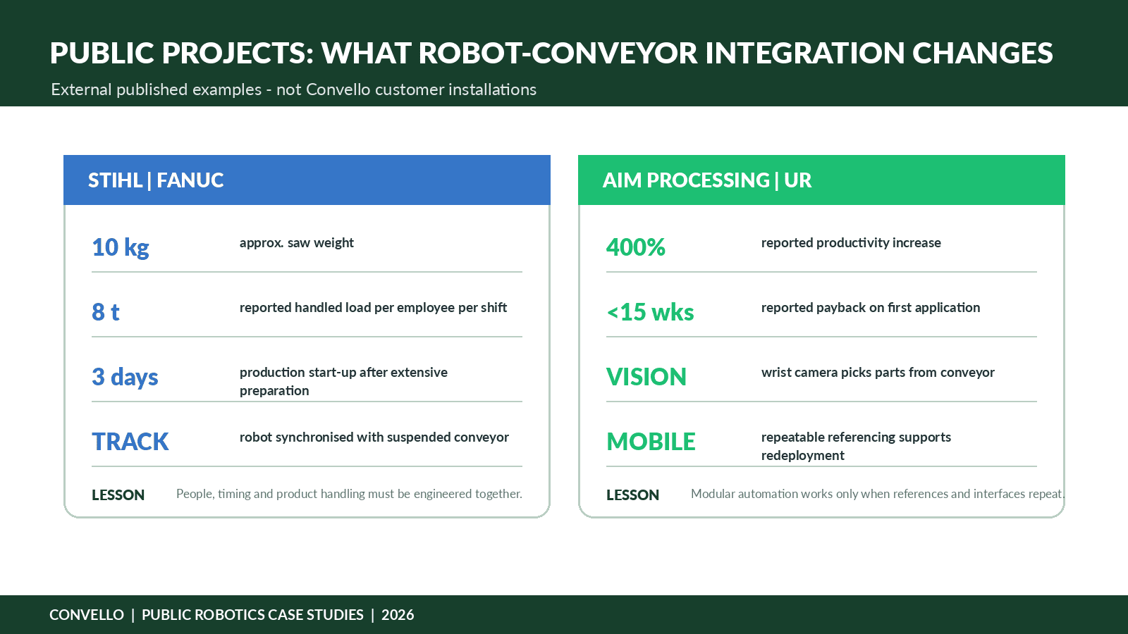
Figure 3. The two public projects show different integration priorities: tracking a moving product and creating repeatable references for flexible deployment.
Illustrative Indian Project: FMCG Carton Palletising Cell
| TRANSPARENCY The following project is an illustrative engineering scenario created for education. It is not a Convello customer installation, quotation or performance guarantee. |
A food and personal-care contract packer operates two shifts. A case sealer discharges three carton sizes weighing between 5 kg and 11 kg. Normal flow is four cartons per minute; peak flow reaches six cartons per minute after short upstream stops. Two operators currently rotate through manual palletising, slip-sheet placement, pallet movement and quality checks.
At an average 4.5 cartons per minute over an eight-hour shift, the station handles about 2,160 cartons. At an illustrative average of 7.5 kg per carton, that represents 16.2 tonnes of cumulative lifted product mass per shift. This number is not an ergonomic risk score, but it makes the repetition visible.
| Cell element | Illustrative design direction |
| Infeed and presentation | Powered roller or belt conveyor, side guides, carton squaring and product-present sensor |
| Identification | Barcode read or recipe selection to confirm SKU and pallet pattern |
| Robot task | Pick the carton and place it according to the active pallet recipe |
| End effector | Vacuum or hybrid gripper validated on all carton surfaces and weights |
| Buffer | Approximately 10 controlled positions as an initial concept for a 75-second pallet-change interruption at peak rate |
| Pallet positions | Two positions so a completed pallet can be removed while the cell works on the alternate position, subject to risk assessment |
| Exceptions | No-read or damaged cartons routed to a controlled manual inspection position |
| Controls | PLC and HMI coordinate conveyor release, robot ready, grip confirmation, pallet status and blocked conditions |
| Safety | Project-specific guarding, scanning, interlocks, safe access and controlled restart |
The acceptance test should use the smallest and largest cartons, imperfect but accepted tape conditions, all pallet patterns, a full destination, a failed grip, a no-read, an emergency stop, power restoration and a pallet change. A cell that only proves the perfect carton during a short demo is not ready for production.
Robot and Cobot Safety: Integrate the Complete Application
The robot is only one part of the hazard picture. The gripper can pinch or drop a product. The conveyor introduces nip and crush points. A pallet can shift. A failed vacuum cup can release a carton. An operator can enter to place a slip sheet, clear a jam or recover a rejected product. Safety must therefore cover the complete application, including foreseeable intervention and maintenance.
ISO 10218-2:2025 addresses integration, commissioning, operation and maintenance of industrial robot applications and cells. ISO/TS 15066 provides additional guidance for collaborative industrial robot systems and work environments. These are planning references, not a replacement for the applicable legal requirements, site standards, manufacturer instructions and project-specific risk assessment.
- Who replenishes empty pallets, cartons, fixtures or trays?
- Where does that person stand while the cell is running?
- How is access detected, stopped and reset?
- What stored energy remains in pneumatic tools, vacuum circuits, lifts or accumulated products?
- How is a failed product recovered without reaching through a hazard?
- What happens after power loss, communication loss or an emergency stop?
- Who is authorised to use manual or teach mode?
ISO 10218-2:2025 covers the integration and lifecycle of industrial robot applications and robot cells. View source
ISO/TS 15066:2016 supplements robot safety guidance for collaborative industrial robot systems and work environments. View source
OSHA describes industrial robot systems as integrated applications that may include conveyors, worktables and process equipment. View source
Commissioning Tests That Expose Real Problems
| Test condition | What to verify |
| Product variation | Run all SKU sizes, weights, surfaces and accepted packaging conditions |
| Rate and recovery | Prove sustained peak flow and queue recovery after a realistic stoppage |
| Tracking | Change conveyor speed within the approved range and verify pick position |
| Grip integrity | Create partial seal, damaged surface and failed-pick conditions |
| Destination blocked | Fill the pallet, tote, machine or outfeed and confirm upstream response |
| Identification | Test no-read, wrong code and recipe mismatch handling |
| Safety and restart | Test access, emergency stop, safe stop, power loss and deliberate restart |
| Changeover | Change SKU, gripper or pallet recipe using the documented method |
| Maintenance access | Demonstrate cleaning, filter change, sensor replacement and calibration checks |
| Data and alarms | Confirm that messages identify what happened, where it happened and who should act |
When a Robot May Not Be the Right First Investment
Robots are valuable when the task is repetitive, measurable and physically or operationally suitable for automation. They are less persuasive when the process changes every day, products cannot be presented reliably, the volume is too low, or the real bottleneck sits elsewhere.
- The upstream process is unstable and produces unpredictable bursts, jams or quality defects.
- The accepted product range cannot be gripped or identified without major packaging changes.
- The task occurs only occasionally and a simple lift assist, fixture or conveyor change would solve the problem.
- The facility needs frequent route changes that a fixed conveyor and robot cell would restrict.
- There is no internal owner for programs, recipes, backups, maintenance and safe recovery.
- The proposed benefit depends on removing people but still requires constant manual correction.
A responsible project may begin with better product presentation, a controlled conveyor, an ergonomic lift assist, a fixture or a short automation pilot. The strongest business case is often created by solving the process first and then selecting the automation.
Ten-Step Robotic Conveyor Integration Roadmap
- Define the operating problem. State the manual effort, quality issue, rate constraint or safety concern in measurable terms.
- Collect real product data. Use photographs, samples, dimensions, weights, surfaces, centres of gravity and accepted variation.
- Map the real flow. Observe normal production, stoppages, changeovers, rejected products and operator workarounds.
- Select the architecture. Choose indexed, tracked, buffered, fixture-based or palletising flow based on the task.
- Prove presentation and grip. Test actual products with the proposed conveyor surface, guides, vision and end effector.
- Size cycle and buffer. Use sustained peak rate, recovery rate and interruption duration, not only average production.
- Define controls and safety. Write handshakes, states, faults, manual modes, access, reset and recovery before coding.
- Simulate and complete FAT. Test normal production and deliberately create the important failure conditions.
- Install and ramp gradually. Start with controlled output, train all shifts and close punch-list items before full release.
- Measure and improve. Track failed picks, manual interventions, microstops, cycle time, changeover and maintenance actions.
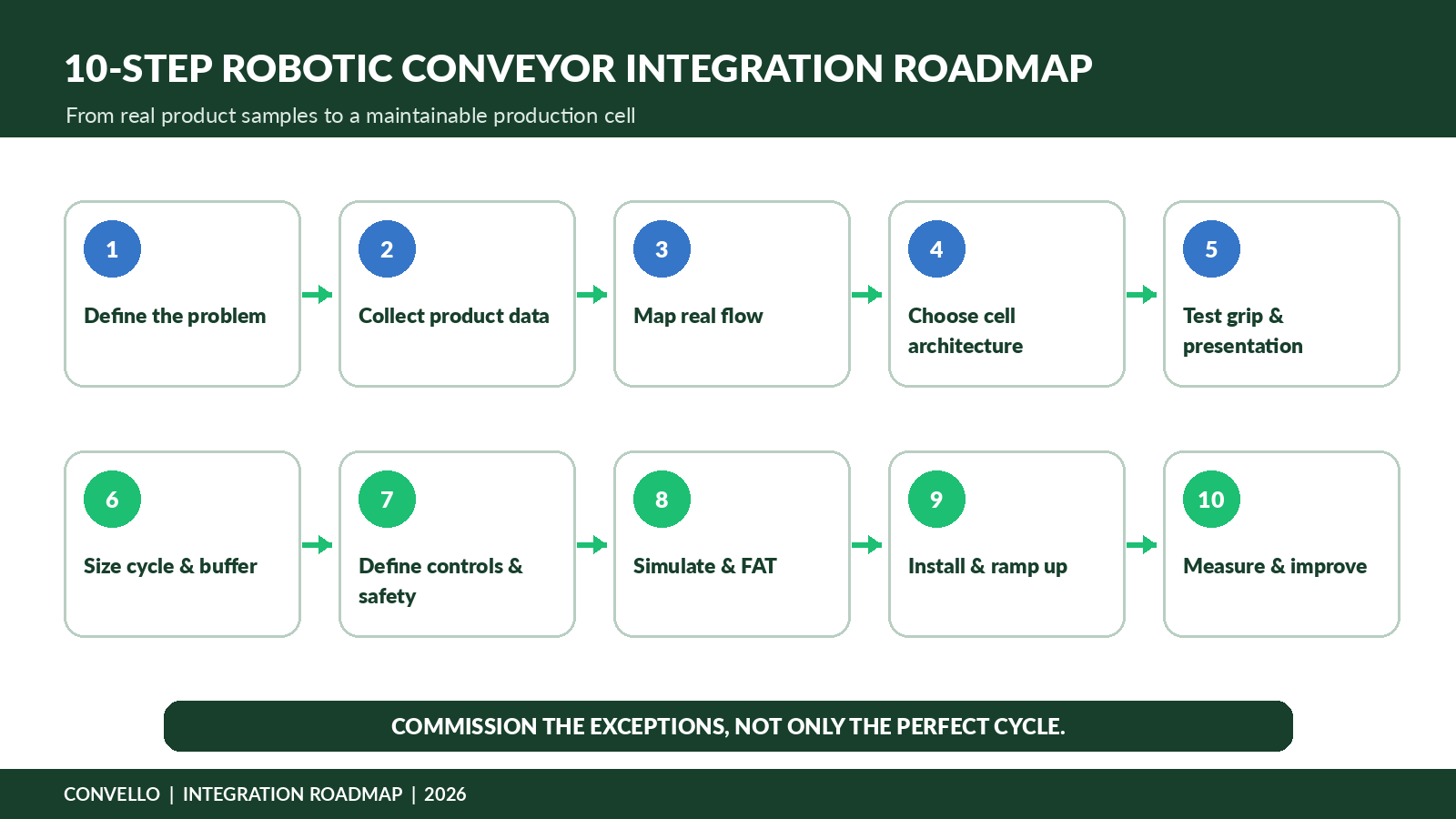
Figure 4. A reliable robotic conveyor project moves from product evidence to integration, testing, training and measured improvement.
Information to Share for an Accurate Quotation
| RFQ area | Information to provide | |
| Product | Photos, samples, dimensions, weight range, surface, stiffness, centre of gravity and accepted defects | |
| Rate | Normal, sustained peak, short burst, shifts, operating hours and expected future volume | |
| Task | Pick, place, orient, inspect, assemble, pack, palletise, depalletise or tend a machine | |
| Current process | Video, operator steps, pain points, intervention frequency and downtime history | |
| Conveyor | Existing or proposed type, speed range, top height, route, transfers and accumulation | |
| Robot cell | Available footprint, ceiling height, reach constraints, payload and preferred location | |
| Grip | Product contact restrictions, vacuum suitability, gripping surfaces and changeover needs | |
| Identification | Barcode, QR, RFID, vision, traceability and recipe requirements | |
| Destination | Pallet, tote, fixture, carton, machine or process interface details | |
| Controls | Existing PLC, HMI, network, I/O standards, upstream/downstream signals and data ownership | |
| Safety | People, forklifts, access tasks, maintenance routes and site standards | |
| Environment | Dust, washdown, oil, temperature, hygiene, noise and utilities | |
| Acceptance | Required rate, quality, failed-pick handling, changeover, documentation and training | |
| CONVELLO ENQUIRY Share the product, rate, layout, robot task, current process video and required interfaces. The conveyor, robot and controls should be reviewed as one operating system, not quoted as disconnected equipment. | ||
Common Robotic Conveyor Integration Mistakes
- Selecting the robot before proving that the product can be presented and gripped consistently.
- Using average production rate instead of sustained peak and recovery flow.
- Expecting vision to compensate for every packaging and orientation problem.
- Ignoring pallet change, full destination, no-read and failed-pick conditions.
- Treating the conveyor as a passive transport device rather than the robot’s product-presentation system.
- Assuming a cobot application is safe because the robot itself has collaborative features.
- Installing sensors without defining the decision and owner behind each signal.
- Testing only perfect products at a slow demonstration rate.
- Failing to provide manual recovery, maintenance access and source-code backups.
- Measuring robot utilisation while operators still perform hidden corrections.
Frequently Asked Questions
1. What is robotic conveyor integration?
It is the coordinated design of a conveyor, robot or cobot, sensors, vision, gripper, controls and safety system so products can be moved and handled reliably as one cell.
2. Can a robot pick products while the conveyor is moving?
Yes. Conveyor tracking can use an encoder and vision or sensor reference to update the product position while the belt moves. The product, speed, tracking hardware and robot work envelope must support the required cycle.
3. Is an indexed conveyor simpler than line tracking?
Often yes. Stopping a product at a repeatable datum can simplify position control, but indexing consumes time and may reduce throughput. The best choice depends on rate and product behaviour.
4. Which robot is best for a conveyor line?
Delta robots suit fast light-product picking, SCARA robots suit small-part planar tasks, six-axis robots provide orientation flexibility, cobots support selected shared-workspace applications, and gantries suit long rectangular travel. Selection must follow the complete task.
5. Can a cobot work beside a conveyor without fencing?
Sometimes, but not automatically. The complete application – including conveyor, gripper, product, pallet and human tasks – requires a risk assessment and suitable protective measures.
6. What information is needed for robot cycle-time calculation?
Product rate, products per pick, robot path, grip and release time, vision time, conveyor speed, destination pattern, changeovers and realistic exception allowances are needed.
7. Why do robot picks fail even when the robot is accurate?
Common causes include unstable product presentation, inconsistent packaging, poor lighting, encoder or calibration issues, insufficient pick window, unsuitable gripping surfaces and unhandled upstream variation.
8. Does every robot-conveyor cell need vision?
No. A fixed fixture or indexed stop may create a reliable datum without vision. Vision becomes valuable when position, orientation, identity or product variation cannot be controlled mechanically.
9. How much buffer should be placed before a robot?
Buffer size depends on arrival rate, interruption duration, product contact rules, floor space and downstream recovery capacity. Calculate positions and confirm the design using real operating scenarios.
10. Can an existing conveyor be integrated with a robot?
Often yes, when its structure, speed control, tracking reference, product presentation, safety and electrical interfaces are suitable. A site audit should identify required modifications.
11. What should be tested during FAT and SAT?
Test the full product range, peak rate, tracking, grip failures, blocked destinations, no-reads, power loss, emergency stops, restart, changeover, maintenance access and documentation.
12. How should ROI be measured?
Include labour redeployment, ergonomic risk reduction, throughput, quality, overtime, downtime, changeover, maintenance, consumables and the cost of continued manual intervention. Use conservative assumptions and verify after start-up.
Conclusion
Robotic conveyor integration succeeds when the product arrives in a condition the robot can understand, grip and place – and when the cell knows what to do if that condition is not met. The robot, conveyor, gripper, vision, controls, safety, operators and maintenance team form one operating system.
A useful project begins with real products, real rates and real intervention points. From there, the conveyor can present the product, the robot can perform the repetitive task, and people can focus on quality, replenishment, maintenance and decisions that require judgement.