+91 99980 88430 | +91 95589 17778
 info@convello.in | sales@convello.in

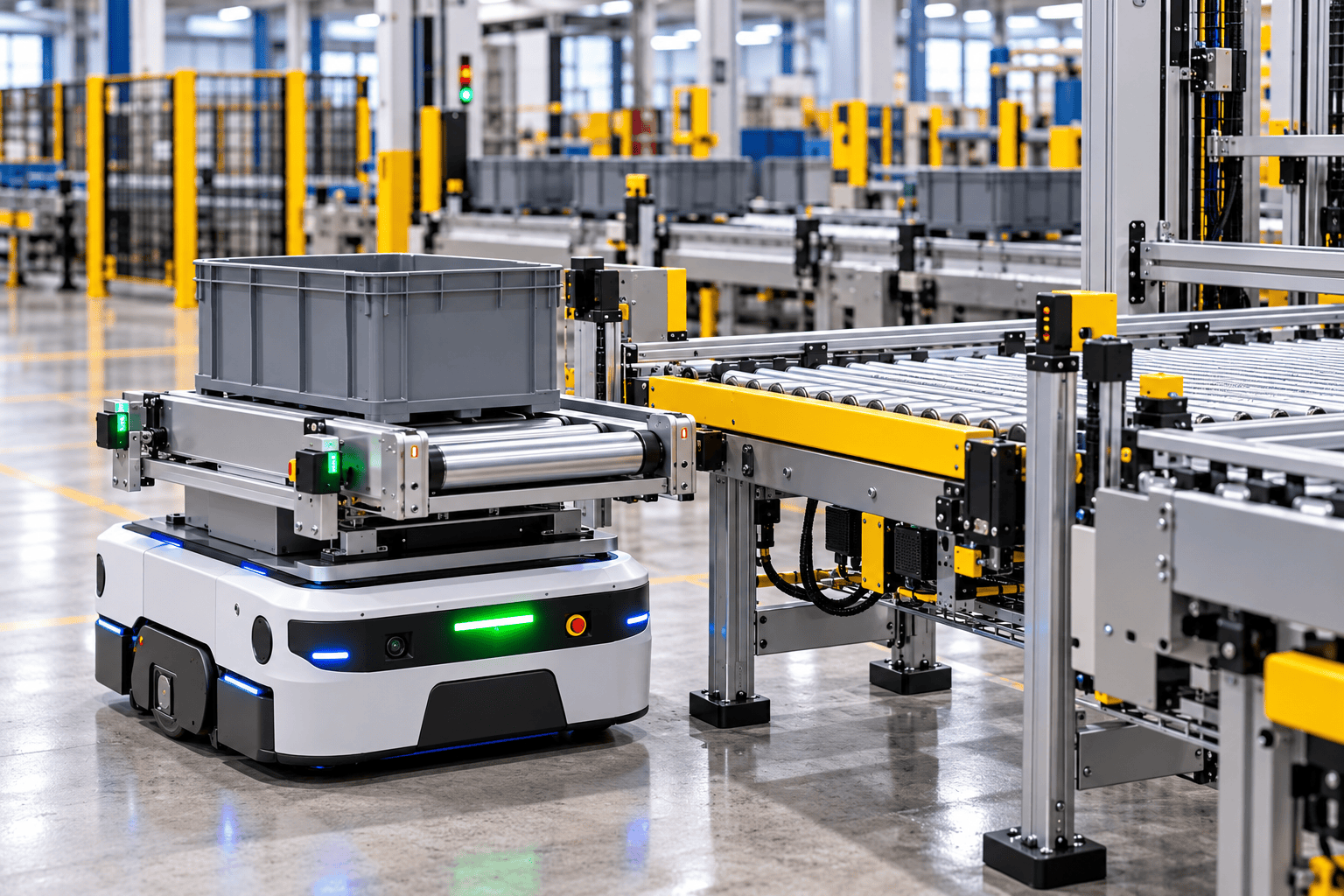
At 3:22 p.m., an autonomous mobile robot reaches Station 4 with a tote of components. The fleet dashboard shows the mission as complete. The robot is facing the correct conveyor, its battery is healthy and its top rollers are ready.
The rollers start. The tote moves forward, touches the side frame of the stationary conveyor and stops halfway across the gap. An operator gives it a short push, confirms that it is clear and returns to the assembly bench. The next three transfers work without help, so the incident is treated as a small inconvenience.
The robot completed the route. The handoff did not.
This opening is an illustrative plant-floor composite, not a claimed Convello customer incident. It reflects a common gap in mobile-robot projects: the travel path receives detailed attention, while the final docking and load-transfer interface is treated as a minor accessory. In reality, the last few hundred millimetres determine whether the project is fully automatic or quietly dependent on people.
| Human reality When operators repeatedly nudge totes, re-square pallets or reset a docking fault, the project may still look automated on a dashboard. The useful question is not only “Did the AMR reach the station?” It is “Did the load transfer correctly, safely and without an unwritten human correction?” |
What Is AMR Conveyor Integration?
AMR conveyor integration connects an autonomous mobile robot with fixed conveyor equipment so a tote, carton, tray, workpiece carrier or pallet can move automatically between mobile and stationary material-handling systems. The robot provides flexible point-to-point transport. The conveyor top module and docking station create the physical handoff. Sensors, controls and software decide when movement is permitted and confirm that it finished correctly.
A complete system normally contains:
- An AMR or driverless industrial truck with a defined payload and operating envelope.
- A mobile top module, such as powered rollers, a belt, lift deck, pallet roller module or cart interface.
- A stationary conveyor or docking station at each pick-up and delivery point.
- Position, load-presence, guard and conveyor-ready sensors.
- A local transfer handshake between the mobile and stationary equipment.
- Fleet software that assigns missions, manages traffic and schedules charging.
- PLC, WCS, MES, WMS or production-system interfaces where required.
- A safe and documented method for partial transfers, blocked destinations, lost communication and manual recovery.
The mobile robot is therefore only one part of the solution. A reliable project also needs a stable product, a compatible conveying surface, repeatable station geometry, useful controls and a recovery process that operators can understand.
AMR, AGV and Conveyor: A Practical Distinction
The terms AMR and AGV are often used loosely. In practical factory discussions, an automated guided vehicle usually follows a more defined guidance method or route, while an autonomous mobile robot is designed to navigate more dynamically around mapped environments and obstacles. The boundary can vary by supplier and application, so the project specification should describe the required behaviour rather than rely only on the label.
The principles in this guide apply to many driverless industrial trucks that transfer loads to fixed conveyors: docking must be repeatable, the load must remain contained, both sides must agree that transfer is safe, and the system must know whether the load is actually on the robot or at the station.
The Seven-Stage AMR Conveyor Handoff
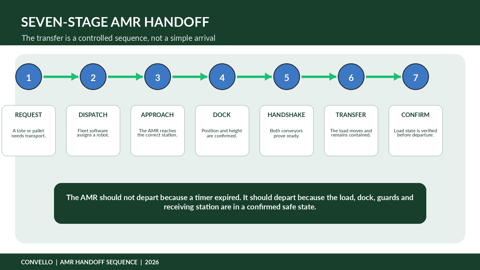
Figure 1. The handoff should be controlled by state and confirmation, not only by a timer.
- Create a transport request. A production cell, operator, warehouse system or sensor creates a mission for a specific load and destination. The request should include load identity, route priority and any process constraints.
- Assign the mission. Fleet software selects a suitable robot based on location, payload, battery, traffic, equipment compatibility and current workload. A robot that is physically nearest may not be the best choice if its top module or charge state is unsuitable.
- Approach the station. The AMR travels to an approach point while coordinating with pedestrians, forklifts, doors, lifts and other robots. The final approach should be designed around the docking geometry rather than treated as an ordinary navigation waypoint.
- Dock and verify position. The robot aligns with the stationary station. Mechanical guides, reflectors, fiducials, optical sensors, infrared devices or other means may be used to confirm position. Height, angle, lateral offset and stopping distance all influence the transfer.
- Complete the local handshake. The mobile and stationary conveyors confirm that the correct station is present, both sides are ready, guards or barriers are in the correct state, the destination has capacity and transfer direction is agreed.
- Transfer the load. The conveyors run in a controlled sequence. Speed and acceleration should protect product stability. The load should remain supported across the gap and contained against rolling or sliding away.
- Confirm and release. Sensors confirm that the load has fully left one side and arrived on the other. Only then should barriers return, the conveyors stop and the AMR depart or accept a new mission.
| A timer is not proof A five-second transfer timer may work during testing and still release an AMR with a partially transferred tote when packaging is damaged, a roller is dirty or the receiving station is blocked. Use positive load-state confirmation wherever the risk justifies it. |
Where AMR Conveyor Integration Is Useful
| Application | How the AMR-conveyor handoff helps |
| Assembly supply | Move totes or workpiece carriers from a supermarket or kitting area to multiple workstations. |
| Work-in-progress transport | Connect machining, washing, inspection and packing cells without building a permanent conveyor route through every aisle. |
| Packing and dispatch | Collect cartons from several packing areas and deliver them to sortation, palletising or dispatch conveyors. |
| Pallet movement | Bridge pallet conveyor islands, stretch wrappers, inspection stations and warehouse lanes where forklift traffic should be reduced. |
| Clean or controlled areas | Move contained materials through defined interfaces while reducing unnecessary manual transport; hygiene and environmental requirements still need application-specific engineering. |
| Multi-floor logistics | Use doors and lifts to connect stores, production and dispatch when a continuous fixed conveyor is impractical. |
| Layout-changing factories | Support cells that move or expand frequently, while retaining fixed conveyors at stable high-volume process points. |
Fixed Conveyor, AMR or Hybrid System?
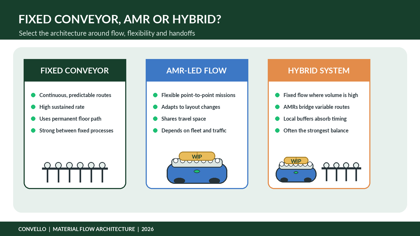
Figure 2. Many successful projects use fixed conveyors for repeatable high-volume flow and AMRs for variable routes between islands.
| Architecture | Strongest use | Main design challenge |
| Fixed conveyor | High, continuous and predictable flow between stable points | Permanent route, transfer engineering, future layout constraints |
| AMR-led flow | Variable point-to-point missions and changing layouts | Fleet availability, traffic, battery, docking and mission queues |
| Hybrid | High-volume fixed zones connected by flexible mobile transport | Clear boundary between conveyor control and fleet control |
A hybrid design is often the most practical. Fixed conveyors can manage accumulation, inspection, packing or machine interfaces. AMRs can carry loads across shared aisles, between buildings or to cells whose locations change. The project should not force every movement into one technology when the flow pattern supports a better combination.
Top Module and Docking Options
| Mobile equipment | Typical use | Important checks |
| Powered roller top | Rigid totes, cartons and many pallets | Matched roller height, product base, load containment and direction control |
| Belt top module | Soft packages, smaller products or loads needing continuous support | Belt friction, edge support, transfer gap and cleaning |
| Lift or under-load module | Carts, racks, pallets or stands designed for pickup from below | Lift stroke, stability, stand geometry and load-centre location |
| Cart or tugger interface | Batch movement where automatic conveyor transfer is not required | Cart coupling, route width, manual touchpoints and train stability |
| Combined lift-and-roller module | Projects needing both under-load pickup and conveyor handoff | Weight, complexity, docking height and complete cycle time |
Interroll’s current LCP AMR Top Module is one example of an integrated light-load approach. Its published specifications describe belt and roller variants, infrared communication with docking stations, payloads up to 50 kg and speeds from 0.11 to 0.30 m/s. These are product-specific values, not universal AMR limits; the correct module must be selected from the actual load, robot and process.
Source: Interroll LCP AMR Top Module – interroll.com/products/lcp/lcp-amr-top-module
Fifteen Design Decisions That Determine Reliability
- Define the complete load range. Record the smallest, largest, lightest, heaviest and least stable accepted load. Include damaged-but-acceptable cartons, worn totes, pallet runner direction and any overhang.
- Use the complete moving payload. Include the load, top module, barriers, sensors, adapters and any fixture. Payload capacity alone does not confirm stability, braking performance or usable battery life.
- Match the conveying surfaces. Roller pitch, belt width, friction, product underside and transfer gap must support the load from the mobile module to the stationary conveyor.
- Control station height and level. Small height differences can create impact, stalls or rolling. Include floor variation, wheel wear, robot suspension, load deflection and station tolerances.
- Engineer docking tolerance. Define allowable lateral, longitudinal and angular error. The robot’s navigation repeatability and the transfer mechanism’s tolerance are different specifications and must be compatible.
- Provide a stable final approach. Avoid placing docking stations where forklifts frequently cross, floors are damaged, people queue or temporary materials block the approach path.
- Use a local transfer handshake. The final transfer should not rely only on a distant software command. Confirm the correct station, robot position, direction, readiness, capacity and barrier state at the interface.
- Confirm load state. Use sensors or other suitable detection to prove that the load is fully on the AMR before travel and fully off the AMR before release.
- Design stationary buffer capacity. A robot may arrive while the process is blocked. Provide enough controlled space or a mission rule that prevents the AMR from becoming a long-term queue.
- Define destination-full behaviour. Decide whether the AMR waits, diverts, returns, uses another station or reports an exception. The answer should be operationally visible.
- Calculate fleet capacity from real mission time. Include loading, transfer, traffic, doors, lifts, waiting, charging and recovery. The shortest empty travel time is not a useful fleet-sizing basis.
- Plan charging around the duty. Opportunity charging, automatic charging and battery strategy should support peak missions, not only the average daily total.
- Design safety at the docking interface. Consider crushing, shearing, nip points, unexpected conveyor motion, rolling loads, pedestrian access and foreseeable attempts to recover a stalled transfer.
- Give faults a recovery method. Define how operators handle partial transfers, wrong loads, sensor disagreement, communication loss, low battery, blocked stations and failed doors or lifts.
- Reserve expansion capacity. Allow for additional destinations, routes, robots, charging points, PLC I/O, network traffic and fleet-software licences where growth is likely.
Fleet Sizing: A Simple Concept-Stage Calculation
A useful first calculation estimates the number of robot-equivalents required during the sustained peak period:
| Concept formula Required robot workload = peak missions per hour × average mission cycle time in minutes ÷ 60. Planned fleet = required workload ÷ target utilisation. |
Consider an illustrative electronics plant requiring 30 tote missions per hour during the peak replenishment window. The measured 95th-percentile mission cycle – including travel, docking, transfer and normal waiting – is eight minutes.
| Input | Illustrative result |
| Peak demand | 30 missions/hour |
| Measured planning cycle | 8 minutes/mission |
| Robot workload | 30 × 8 ÷ 60 = 4.0 robot-equivalents |
| Target utilisation | 75% to retain recovery capacity |
| Concept-stage fleet | 4.0 ÷ 0.75 = 5.33, rounded to 6 robots |
This does not prove that six robots will work. Traffic conflicts, elevator queues, charging, station waiting, route priority, maintenance availability and mission variability require simulation or detailed operational analysis. The purpose of the formula is to expose unrealistic fleet estimates early.
Illustrative Indian Project: Linking a Store to Six Assembly Cells
Consider a concept-stage project in an Indian electrical-equipment plant. A central supermarket prepares standard totes for six assembly cells. Operators currently collect totes with hand trolleys, return empty containers and sometimes delay replenishment until a station is almost empty.
The proposed hybrid system uses short powered roller conveyors at the supermarket and each assembly cell, combined with AMRs carrying roller top modules. The fixed stations provide repeatable loading and a two-tote buffer. The AMRs bridge shared aisles without installing a permanent conveyor across forklift routes.
| Project input | Illustrative requirement |
| Load | 600 × 400 mm totes, 5-22 kg, rigid base |
| Peak demand | 30 loaded-tote missions/hour plus empty returns |
| Destinations | Six assembly cells and one supermarket |
| Docking | Matched powered roller stations with local ready/position/load handshake |
| Controls | Fleet manager + station PLC + production replenishment request |
| Exception route | Manual recovery bay for damaged totes or uncertain load state |
| Safety focus | Shared aisles, docking nip points, rolling load containment and controlled restart |
The project team should test the least favourable tote, not only a clean empty sample. A bowed base, uneven load or projecting label can change transfer behaviour. Operators should participate in the station review because they know where trolleys are left, where people gather at shift change and which aisle is blocked during material counts.
| Project lesson The AMR replaces travel only when the store, cell, buffer, request logic, empty-return method and recovery bay are designed together. Otherwise, the robot may simply deliver congestion more consistently. |
Public Project Case Study: Honeywell’s Multi-Floor Material Transport
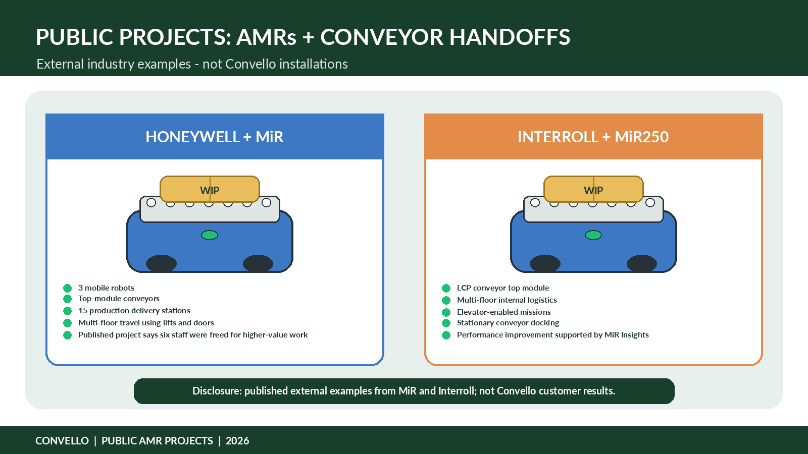
Figure 3. External public projects show how top-module conveyors, fixed stations, doors, lifts and software become one intralogistics system.
Honeywell Safety & Productivity Solutions in Poole, United Kingdom, used three MiR mobile robots to automate internal material transport across a multi-storey manufacturing facility. The published case describes narrow corridors, double fire doors and lift travel between the warehouse and manufacturing areas.
The implementation began in phases. Early workflows used manually loaded robots. Honeywell later developed conveyor interfaces so the robots could collect material from a stationary conveyor and deliver it automatically to production. The published project reports 15 delivery stations and says the solution freed six full-time staff members for higher-value work.
The important lesson is not simply that a mobile robot can use a lift. Honeywell connected navigation, doors, elevators, top-module conveyors, destination logic and production requirements. A robot that only reaches the correct floor would not have delivered the same operational result.
External public project; not a Convello installation. Source: Mobile Industrial Robots – Honeywell Safety & Productivity Solutions – mobile-industrial-robots.com/cases/honeywell-safety-productivity-solutions
Supporting Public Project: Interroll’s MiR250 and LCP Top Module
Interroll also published a project using a MiR250 with its LCP AMR conveyor top module. The robot navigates a multi-floor environment, uses elevators and connects to production lines through the mobile conveyor module. Interroll also uses MiR Insights to analyse fleet behaviour, mission patterns and inefficiencies.
This example reinforces a second lesson: after the mechanical handoff works, the operation still needs data. Waiting time at stations, repeated docking attempts, transfer faults, route congestion and charging patterns can reveal whether the system is truly improving material flow or only moving the old delays to new locations.
External public project; not a Convello installation. Source: Mobile Industrial Robots – Interroll case study – mobile-industrial-robots.com/cases/interroll
Safety at the AMR-Conveyor Interface
AMR safety is not limited to obstacle detection while the robot travels. The docking station creates additional hazards: moving rollers, pinch points, rolling loads, barriers, lift mechanisms, unexpected starts and people reaching into a partial transfer.
ISO 3691-4:2023 covers safety requirements and verification for driverless industrial trucks and their systems, including vehicles commonly described as AGVs or AMRs. The operating zone has a significant effect on safe operation. The complete project should also apply machinery risk-assessment principles to the conveyor interface and any associated equipment.
- Prevent conveyor operation until the AMR is correctly positioned and the correct station is identified.
- Prevent AMR departure until the load is fully contained and the top module is in its travel-safe state.
- Control access to moving rollers, barriers, lift mechanisms and nip points.
- Define what happens after an emergency stop, power loss or communication interruption.
- Provide a safe manual or maintenance mode for recovery and inspection.
- Include foreseeable misuse, such as an operator pushing a stalled load or stepping into the dock to clear it.
- Validate floor condition, slopes, edges, doors, lifts, charging areas and mixed traffic routes.
Safety planning reference: ISO 3691-4:2023 – iso.org/standard/83545.html
Controls and Communication: Separate Route Control from Transfer Control
Fleet software is responsible for missions, route allocation, traffic and charging. The local station control is responsible for the physical transfer. The two layers must cooperate, but they should not be confused.
| Control layer | Typical responsibility |
| Fleet manager | Assign robot, plan route, manage traffic, charging and mission priority |
| AMR controller | Navigate, dock, report state and control the mobile top module |
| Station PLC/controller | Manage stationary conveyor, buffer, barriers, sensors and local permissives |
| WMS/MES/production system | Create demand, identify loads, select destination and record completion |
| Safety system | Monitor safety devices and enforce safe motion states |
Some systems use Wi-Fi or enterprise networks for mission data, while the final transfer confirmation may use a local optical, infrared, wired or other dedicated handshake. ROEQ, for example, describes a sensor-based GuardCom interface between AMR top rollers and stationary stations. The appropriate architecture depends on the project, but the final transfer must remain predictable when enterprise communications are delayed or interrupted.
Technology example: ROEQ GuardCom system – roeq.dk/guardcom-system-lowers-the-barrier-to-automation/
Commissioning Tests That Matter
| Test condition | What to verify |
| Normal transfer | Minimum, maximum and least stable loads at every station |
| Docking repeatability | Repeated approaches from different routes and traffic conditions |
| Height and floor variation | Loaded and unloaded robot, worn wheels, uneven or repaired floors |
| Blocked destination | Station full before arrival and becoming full during transfer |
| Partial transfer | Load stops across the gap; system must detect and hold a safe state |
| Sensor disagreement | One sensor blocked, dirty, failed or giving an unexpected sequence |
| Communication loss | Before docking, during transfer and after load confirmation |
| Emergency stop | AMR, station and surrounding equipment; verify controlled restart |
| Door or lift fault | Robot waits safely and mission does not become lost or duplicated |
| Low battery / charger unavailable | Mission reassignment and safe queue behaviour |
| Manual recovery | Operator instructions, access, isolation and completion record |
| Peak fleet test | Multiple robots, busy routes, full stations and realistic mission priorities |
Ten-Step AMR-Conveyor Project Roadmap
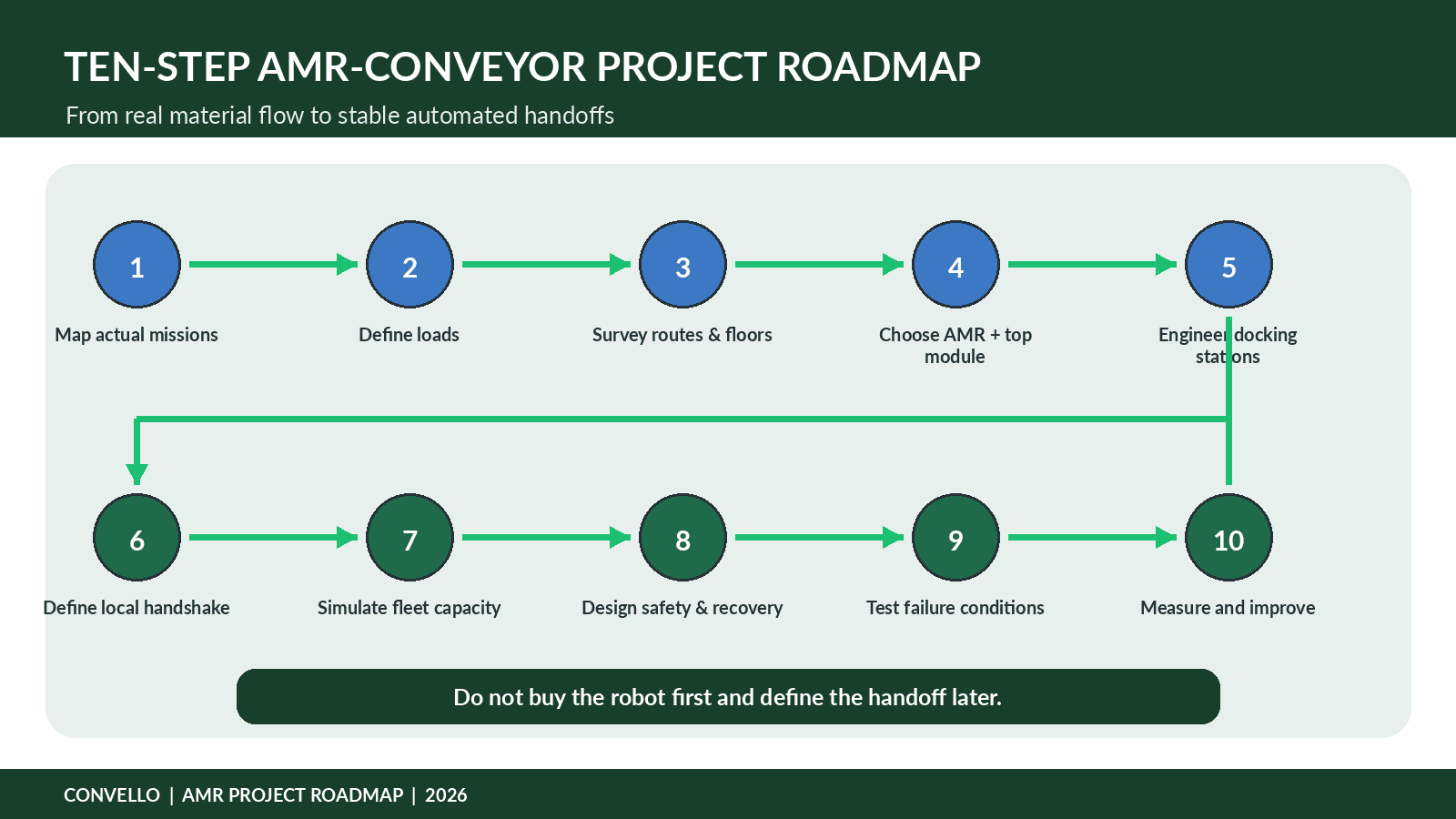
Figure 4. Start with real missions and interfaces, then select the robot and equipment.
- Map actual material missions. Record origins, destinations, load types, timing, queues, human travel and exception routes.
- Define the load and process. Measure dimensions, weight, underside, stability, identity and required orientation.
- Survey the operating environment. Map floors, aisles, slopes, doors, lifts, pedestrian routes, forklifts, Wi-Fi and charging space.
- Choose the architecture. Decide which sections should remain fixed conveyor, which should be mobile and where buffers are needed.
- Select AMR and top module. Match payload, dimensions, route, station type, speed, duty and safety concept.
- Engineer docking stations. Define height, support, guides, sensors, barriers, buffer capacity and maintenance access.
- Define controls and ownership. Write mission, handshake, identification, fault, timeout, manual and recovery states.
- Simulate or model fleet capacity. Use peak missions, measured cycle distributions, traffic and charging rather than average travel time.
- Test normal and failure conditions. Complete FAT, site tests and production trials with representative loads and operators.
- Measure and improve. Track mission time, station waiting, docking retries, transfer faults, manual interventions and service availability.
Information to Share for an AMR Conveyor Integration Quote
- Load dimensions, weight range, underside photographs, stability and centre of gravity.
- Tote, carton, tray, fixture or pallet standards, including worn or damaged-but-accepted conditions.
- Origin and destination list with floor plans, elevations and station photographs.
- Peak missions per hour, daily operating hours, shift pattern and required response time.
- Current manual transport method, travel distance, queue points and operator interventions.
- Required mobile top module: belt, roller, lift, pallet or cart interface.
- Station conveyor type, height, buffer capacity, transfer direction and product orientation.
- Door, lift, airlock, fire-door and traffic-control interfaces.
- WMS, MES, ERP, WCS, PLC, barcode, RFID or production-system requirements.
- Network, cybersecurity, user-access and data-retention expectations.
- Safety standards, site rules, guarding expectations and emergency-response process.
- Charging strategy, available electrical supply and desired fleet availability.
- Installation constraints, production shutdown windows, FAT/SAT and acceptance criteria.
- Required drawings, source code, backups, manuals, training and spare parts.
Common AMR Conveyor Integration Mistakes
- Buying the robot before defining the handoff. The route may work while station height, transfer surface or load containment remains incompatible.
- Sizing from nominal payload only. Payload does not confirm dimensions, centre of gravity, stopping behaviour or top-module mass.
- Using the shortest travel time. Real cycles include waiting, docking, transfer, doors, lifts, traffic, charging and recovery.
- Providing no buffer. The AMR becomes the buffer and cannot serve other missions when a destination is blocked.
- Relying on a timer for transfer confirmation. Damaged loads, dirty rollers and partial transfers require positive state detection.
- Ignoring empty-return flow. Totes, pallets and fixtures often need a planned reverse mission.
- Leaving recovery logic until commissioning. Partial transfer, wrong load, lost communications and full stations must have defined responses.
- Testing only on a clean floor. Dust, thresholds, floor repairs, slopes and wheel wear affect docking and navigation.
- Treating fleet and conveyor controls as separate projects. Unclear ownership creates duplicated commands, missing confirmations and difficult fault finding.
- Measuring robot utilisation instead of business flow. A busy fleet can still create late replenishment, blocked stations and manual interventions.
Frequently Asked Questions
What is AMR conveyor integration?
It is the connection of an autonomous mobile robot and a fixed conveyor so loads can transfer automatically through coordinated docking, controls, sensors and confirmation.
Can an AMR transfer cartons or totes without an operator?
Yes, when the robot uses a suitable belt or roller top module and the stationary station provides compatible height, support, communication and load detection.
Can AMRs move pallets between conveyor lines?
Yes, with an AMR, top module and station engineered for the pallet type, payload, runner direction, load stability, floor condition and required safety measures.
How accurate must docking be?
There is no universal value. The robot repeatability, station guides, transfer gap, product base and conveying surface must be engineered as one tolerance chain.
Does the transfer need Wi-Fi?
Mission systems often use wireless networks, but the final transfer may use a local optical, infrared, wired or other dedicated handshake. The architecture should remain predictable during communication delays or loss.
How many AMRs are needed?
Estimate peak missions multiplied by measured mission cycle time, then divide by 60 and by a realistic target utilisation. Detailed fleet simulation should include traffic, charging, waiting and failures.
What happens when the destination conveyor is full?
The system should have a defined rule: wait at a safe buffer, divert, return, use another station or create an exception. The AMR should not dock blindly into a blocked station.
How is an incomplete transfer detected?
Load-presence sensors, front and rear cargo sensors, conveyor current, position sensing or other validated detection can confirm whether the load is fully on or off the robot.
Can an AMR use elevators and automatic doors?
Yes, when the fleet system and building interfaces are engineered and tested. Public projects such as Honeywell and Interroll describe multi-floor operation with doors or lifts.
Is an AMR safer than a forklift?
The risk profile is different, not automatically absent. The route, speed, load, docking station, mixed traffic, conveyor pinch points and recovery tasks require project-specific risk assessment.
Should we choose AMRs or fixed conveyors?
Use fixed conveyors for stable high-volume flow, AMRs for flexible point-to-point missions and a hybrid system when both conditions exist.
What should be tested before acceptance?
Test representative loads, repeated docking, blocked destinations, partial transfers, sensor faults, communication loss, emergency stops, charging, traffic and manual recovery.
Final Takeaway: Engineer the Handoff, Not Only the Route
An AMR can navigate accurately, avoid obstacles and report a completed mission. None of those capabilities guarantees that a tote or pallet will transfer correctly to a fixed conveyor. The handoff depends on product support, matched heights, repeatable docking, local communication, load confirmation, buffers, safe recovery and clear control ownership.
The strongest projects usually combine technologies. Fixed conveyors manage stable, high-volume process zones. AMRs connect changing routes and distant islands. Operators and maintenance teams help identify the practical conditions that drawings miss. Controls make the normal flow and the exception flow visible.
Convello can support the fixed-conveyor side of an AMR integration project with roller, belt, pallet, cross-transfer and assembly-line conveyor systems designed around the actual load, route, throughput and control interface. Share your load data, floor plan, station list, mission profile and automation requirements to begin an application-specific discussion.